Section A.1
GENERAL DESCRIPTION
The engine is a six cylinder unit with the bores cast integral with the crankcase. Adequate cooling under the most arduous operating conditions is ensured by the provision of large area water circulating passages, and full length water jackets.
The detachable cylinder head is of cast iron and carries the overhead push rod operated valve gear.
Forged steel is used for the counter balanced crankshaft which is supported by four large diameter main bearings of the preformed Thinwall
type. The same type of bearings are used for the connecting rod big end assemblies.
Particular attention has been paid to the design of the lubrication system to ensure that the moving parts of the engine are adequately supplied with oil at all times. The choice of oils is of great importance and those recommended on page Q.1 have been tested under various running conditions and should be used in accordance with the schedule of regular attentions.
Section A.2
VISUAL INSPECTION
Examine the engine for any signs of oil leakage, with particular attention to the sump drain plug, the joint between the oil filter bowl and its head casting, and the rocker cover to cylinder head joint.
The connections to the distributor should be checked occasionally for tightness, and any perished or cracked high tension leads renewed.
Section A.3
ADJUSTMENTS IN THE VEHICLE
The purpose of the following adjustments is to maintain the performance of the engine at its maximum, and consists of a series of cleaning, inspecting and adjusting operations. A compression test of each cylinder should first be made to determine the general condition of the engine before proceeding with any adjustments. If a compression gauge is not available, a simple method to test the compression is to remove all the sparking plugs with the exception of the one in the cylinder being tested, and then rotate the engine with the starting handle through at least two complete revolutions. If the cylinder compression is satisfactory, proceed as detailed below, otherwise the specific fault should be diagnosed by referring to Fault Diagnosis
, Section A.31.
- Clean the engine generally and lubricate as indicated on the lubrication chart.
- Adjust the fan belt tension in accordance with the instructions given in Section C.
- Remove the valve gear cover and test the cylinder head studs for tightness, using a torque spanner set to the figures quoted under
General Data
. - Check and adjust the valve and rocker clearances as outlined in Section A.11.
- Check for evidence of cracked valve springs or scored or worn stems.
- Replace the valve gear cover, using a new gasket if necessary.
- Disconnect the high-tension cables and remove the sparking plugs.
- Check to make sure that the correct type of sparking plug is being used.
- Clean the sparking plugs and examine the insulation for breaks or cracks.
- Adjust the sparking plug gaps as specified in Section B.
- Test the sparking plugs and renew any found to be unfit for further service.
- Refit the sparking plugs, using new copper washers.
- Check the high tension cables for wear and deterioration before refitting.
- Remove the distributor head cover and clean it inside and out. Examine it for cracks and burned contacts and renew it if necessary.
- Inspect the contact breaker points to determine whether new points are needed. Follow the procedure given in Section B to clean and adjust the points.
- Check the distributor rotor arm, making sure the carbon brush makes contact. Check the capacitor terminal to make sure it is clean and tight.
- Check the ignition timing as outlined in Section B.
- Clean the air cleaners in accordance with the instructions in Section D.
- Make sure the fuel system is operating properly and clean all filters in the system as detailed in Section D.
- Check the carburetter flange gaskets for evidence of leakage.
- Adjust the carburetters if necessary, in accordance with the procedure given in Section D.
Section A.4
ENGINE ASSEMBLY
To remove (without gearbox)
- The battery master switch, which is situated inside the luggage compartment, should be turned to the
off
position.
- Remove the radiator as described in Section C and detach the fan by unscrewing the four securing setpins.
- Disconnect the throttle linkage and choke control cable. The throttle linkage is freed by unclamping the throttle control rod at its projection from the bulkhead.
- Unscrew the setpins securing the air cleaners to the carburetter inlets and remove the air cleaners.
- Disconnect the petrol feed pipe at its carburetter union.
- Remove the high tension cables from their connections at the coil and the sparking plugs.
- Release the generator, distributor and coil low tension cables, and place the complete harness to one side.
- Release the heater inlet and outlet rubber hoses from their connections at the rear of the cylinder head and the heater outlet pipe (when fitted).
- Remove the distributor as described in Section B.
- Remove the generator, complete with coil, as described in Section N.
- Remove the external oil filter as described in Section A.6.
- Release the oil pressure flexible pipe at its upper connection.
- Remove the starter motor as described in Section N.
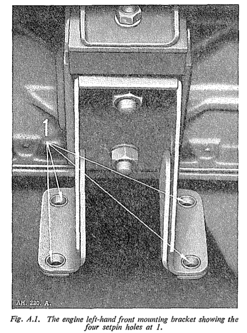
- Withdraw the four setpins which secure each engine mounting bracket to the chassis frame. Detachment of the left-hand bracket is facilitated by a slit in the carburetter heat shield.
- Unscrew the six brass nuts securing the exhaust down pipe to the exhaust manifolds, and pull the down pipe away from the manifold studs.
- Remove the valve rocker as described in Section A.11 and secure two suitable lifting brackets.
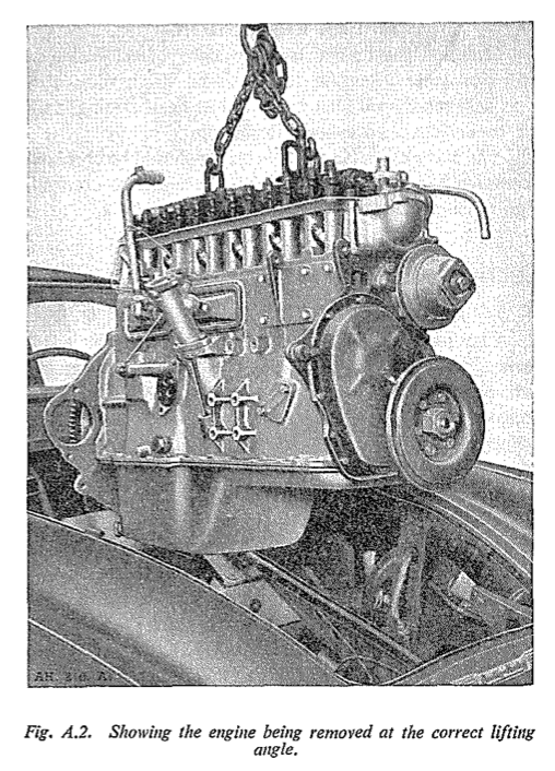
- By means of lifting tackle, similar to that illustrated in fig. A.2, support the engine so that the engine mounting brackets are just clear of their chassis mountings.
- Unscrew the four setpins securing the right-hand engine mounting bracket to the cylinder block and withdraw the mounting.
- Place a suitable support underneath the gearbox bell housing and unscrew the nuts, bolts and setpins securing the bell housing to the engine backplate.
- Hoist the engine to give clearance between the crankshaft damper and the chassis cross member and pull the engine forward so that the clutch driven plate slides off the first motion shaft splines when the engine can be lifted through the bonnet opening and clear of the car.
To Replace
Replacing the engine is the reverse of the procedure To Remove
To Remove (with gearbox)
To avoid possible damage, either to individual components or to the car, removal of the generator, distributor and right-hand mounting bracket is advised.
- Follow the instruction (1) to (10) and (12) to (18) as detailed in the engine removal less gearbox.
- Inside the car remove the seat cushions and release the clips securing the padded arm rest to Note.-When an overdrive gearbox is fitted it the central tunnel.
- Unclip and roll back the carpet over the short gearbox tunnel to expose the twelve screws securing the tunnel to the body of the car. Unscrew the setscrews and remove the tunnel and its carpeting.
- Unscrew the six setscrews, three either side, which secure the carpet covered bulkhead and remove the bulkhead.
- Using a suitable tool tap back the locking washers on the propeller shaft flange bolts and remove the bolts.
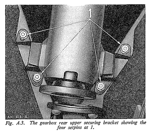
- Unscrew the four setpins from the gearbox mounting brackets (see fig A.3), also unscrew the speedometer cable at its connection to the gearbox.
Note.— When an overdrive gearbox is fitted it will also be necessary to unclip the cable to the gearbox switch and release it at its terminal on the switch
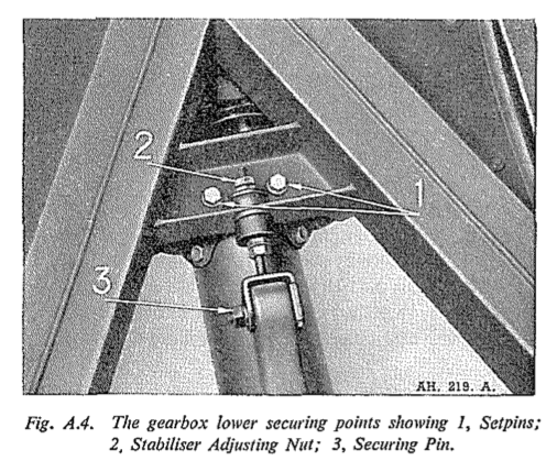
- Working beneath the vehicle remove setpins (1) fig A.4 and unscrew the nuts (2) and (3) to release the stabiliser bar.
- Detach the clutch slave cylinder from the gearbox bell housing by removing the two securing setpins. The slave cylinder push rod is released from the clutch operating lever by the removal of the securing clevis pin.
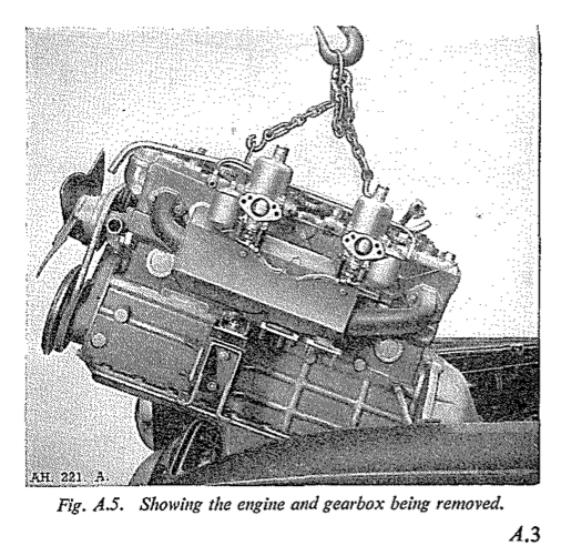
- Hoist the engine complete with gearbox through the bonnet opening as shown in fig. A.5, ascertain that no damage is done by the gearbox when manoeuvring it through the bulkhead aperture.
Section A.5
LUBRICATION
Description
The oil supply is carried in the sump below the cylinder block and the filler cap is fitted on the forward end of the rocker cover. The dipstick is on the righthand side of the engine and is marked to indicate the maximum and minimum levels. The eccentric rotor type oil pump driven by the camshaft is mounted below the crankcase and is partially submerged in the oil reservoir.
Oil is drawn through a gauze strainer secured to the oil pump and passes through a drilling up the right
hand side of the crankcase to the oil filter, passing the non-adjustable pressure relief valve. After leaving the full flow filter the oil-way divides, one drilling passing up the right-hand side of the cylinder block through the cylinder head to a pipe feeding oil to No. 4 rocker shaft bracket. From here, oil passes through the hollow centre of the rocker shaft to lubricate all rocker bearings, and through drillings in the rockers, to lubricate the valve gear. Oil returning to the sump from the rockers lubricates the tappets. The second oilway from the oil filter passes round No. 3 camshaft bearing, (lubricating this bearing as it does so), to the oil gallery on the left-hand side of the engine. From the gallery, drillings in the cylinder block take oil to each main bearing and through the crankshaft to the big ends. Oil-ways from the main bearings also supply the camshaft bearings. The connecting rods have jet holes - to deliver oil to the cylinder walls.
A vent pipe is attached to the rear tappet chamber cover and a breather in the valve rocker cover is connected to the rear air cleaner.
An oil pipe connects the rear end of the main oil gallery on the left-hand side of the engine with the oil gauge on the instrument panel.
Draining the Sump
The sump must be drained and filled with new oil at intervals of 3,000 miles (4800 km.).
The hexagon-headed sump drain plug is at the rear on the right-hand side.
The sump should be allowed to drain for at least ten minutes before the drain plug is replaced. The oil will flow more readily if it is drained while the engine is hot. When the sump has been drained, approximately 10 ¼ pints (12.3 U.S. pints, 5.85 litres) of oil are required to fill it. The capacity of the filter is approximately 1¼ pint (1.5 U.S. pints, 0.84 litres), giving a total of 11½ pints (13.8 U.S. pints, 6.55 litres). Do not forget to replace the sump drain plug.
Never use petrol or paraffin; for flushing purposes. Such cleaning mediums are never completely dispersed from the engine lubrication system, and will remain to contaminate any fresh oil. This may cause premature bearing failure.
At every alternate oil change, or every 6,000 miles (9600 km.), a new external oil filter element should be fitted.
Refilling
When refilling the sump do not pour the oil in too quickly, as it may overflow from the filler orifice and
mislead the operator as to the quantity of lubricant in the engine.
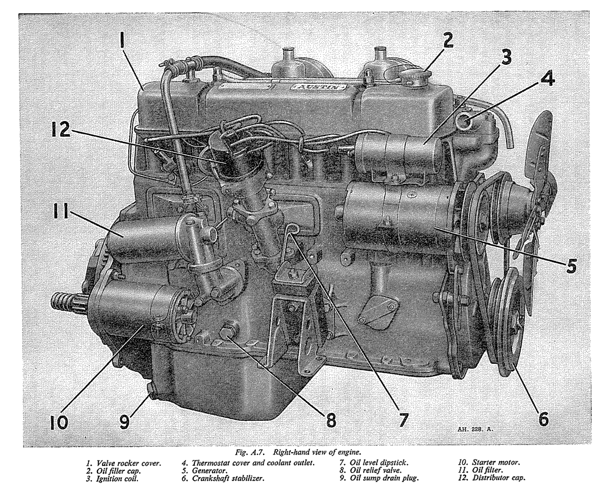
Before testing the level of the oil, ensure that the vehicle is as near level as possible. Always wipe the dipstick clean with a non-fluffy cloth before taking the reading. It should be remembered that time must be allowed for new oil to reach the sump before reading the dipstick. The dipstick location is shown in fig A.7.
Oil Pressure
The pressure indicated by the gauge may rise to 60 lb. per sq. in. when the engine is started up from cold, but after the oil has circulated and become warm, the pressure will drop to approximately 55 lb. per sq. in., with a proportionately lower idling pressure, (about 25 lb. per sq. inch). If no oil pressure is registered by the gauge, stop the engine at once and investigate the cause.
NOTE: The automatic relief valve in the lubrication system deals with any excessive oil pressure when starting from cold.
Continuous running with unnecessary use of the mixture control is often the cause of serious oil dilution by petrol, and a consequent drop in pressure.
Check for Low Oil
Check the level of oil in the engine sump by means of the dipstick and top up if necessary. Ascertain that the gauze strainer in the sump is clean and not choked with sludge, also that there is no air leakage at the strainer union on the suction side of the pump.
In the unlikely event of the oil pump being defective, remove the unit and rectify the fault, see Section A.8. The oil relief valve should be examined, see Section A.9.
If the engine bearings are worn the oil pressure will be reduced. A complete bearing overhaul and the fitting of replacement parts is the only remedy, necessitating the removal of the engine from the chassis.
Section A.6
OIL FILTER
The external filter is a full Bow type thus ensuring that all oil in the lubrication system passes through the filter before reaching the bearings.
The element of the filter is of star formation in which a special quality felt, selected for its filtering properties, is used.
Oil is passed to the filter from the pump at a pressure controlled at 50/55 lb. per sq. inch by the engine oil relief valve. Some pressure is lost in passing the oil through the filter element; this will only be a pound or two per square inch with a new element, but will increase as the element becomes progressively contaminated by foreign matter removed from the oil.
Should the filter become completely choked due to - neglect, a balance valve is provided to ensure that oil will still reach the bearings. This valve, set to open at a pressure difference of 15/20 lbs. per square inch, is non-adjustable and is located in the filter head casting. When the valve is opened, unfiltered oil can by-pass the filter element and reach the bearings.
To renew the filter element proceed as follows :-
- Unscrew and remove the tachometer drive from the distributor housing.
- Remove the two setpins securing the filter bracket to the crankcase.
- Unscrew the centre fixing bolt, and the container complete with element can be removed.
- Withdraw the contaminated element and carefully cleanse the container of all foreign matter that has been trapped.
- After ensuring that no fibres from the cleansing operation have been left in the container, put in a new element, prime the filter and refit to the head - casting, tightening the centre fixing bolt sufficiently to make an oil-tight joint.
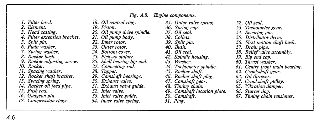
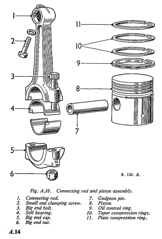
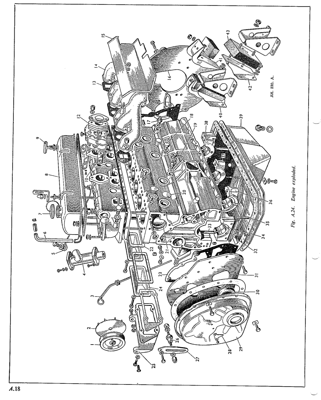
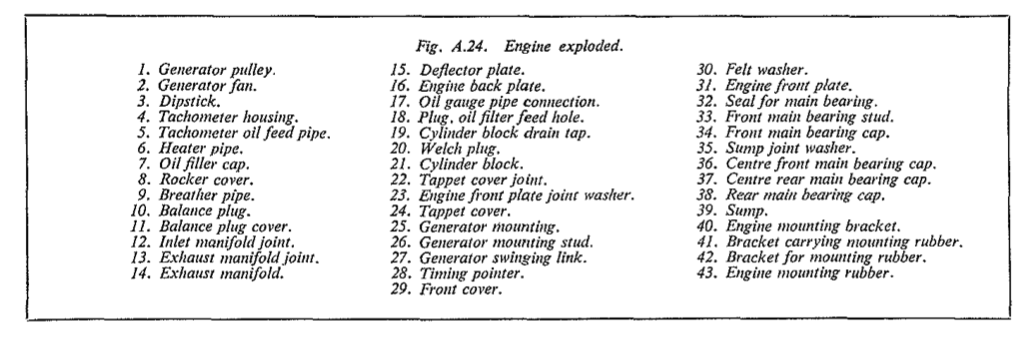
Fig. A.8. Engine components. 1. Filter bowl. 2. Element. 3. Head casting. 4. Filter extension bracket. 5. Split pin 6. Plain washer. 7. Spring washer. 8. Rocker bush. 9. Rocker adjusting screw. 10. Rocker. 11. Spacing washer. 12. Rocker shaft bracket. 13. Spacing spring. 14. Rocker oil feed pipe. 15. Push rod. 16. Gudgeon pin. 17. Compression rings. 18. Oil control ring. 19. Piston. 20. Oil pump drive spindle. 21. Oil pump body. 22. Inner rotor. 23. Outer rotor. 24. Bottom cover. 25. Pick-up stainer. 26. Shell bearing big end. 27. Connecting rod. 28. Tappet. 29. Camshaft bearings. 30. Exhaust valve. 31. Exhaust valve guide. 32. Inlet valve. 33. Inlet valve guide. 34. Inner valve spring. 35. Outer valve spring. 36. Spring cap. 37. Oil seal. 38. Collets. 39. Split pin. 40. Bush. 41. Oil seal. 42. Spindle housing. 43. Washer. 44. Tachometer spindle. 45. Rocker shaft. 46. Rocker shaft plug. 47. Camshaft gear. 48. Timing chain. 49. Camshaft location plate. 50. Camshaft. 51. Plug. 52. Oil seal. 53. Tachometer gear. 54. Securing pin. 55. Distributor drive. 56. First motion shaft bush. 57. Drain pipe. 58. Relief valve assembly. 59. Big end cap. 60. Thrust washer. 61. Centre front main bearing. 62. Crankshaft gear. 63. Oil thrower. 64. Crankshaft pulley. 65. Vibration damper. 66. Starter dog. 67. Timing chain tensioner.
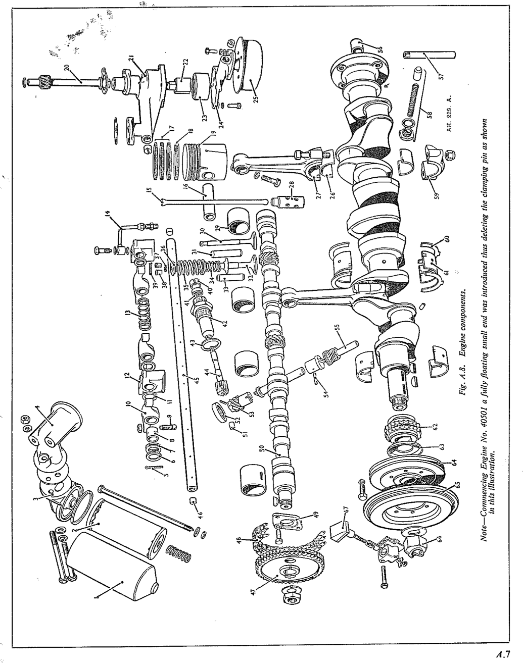
Note - Commencing Engine No. 40501 a fully floating small end was introduced thus deleting the clamping pin as shown in this illustration.
- Replace the filter and bracket complete by means prevent it falling out. Note also the thrust washer of the two setpins. fitted on the drive shaft above the gear.
- Refit the tachometer drive to the distributor housing.
- Check the level of oil in the sump by means of the dipstick.
It is recommended that the filter container should not be disturbed other than for cleaning and the fitting of a new element at the recommended mileages; to do so invites the hazard of added contamination from accumulated dirt on the outside of the filter entering the container, and thus being carried into the bearings on restarting the engine.
Section A.7
SUMP AND GAUZE STRAINER
Removing
- Drain off the oil into a suitable container then extract the setscrews and washers, thus enabling the sump to be removed.
- Detach the bottom of the strainer by removing the nut, washer and distance piece. Take out the three setpins holding the strainer to the pump, so allowing the body of the gauze strainer to be removed. The pump and strainer can be swilled out with petrol or paraffin and thoroughly dried with a non-fluffy rag.
- Inspect the two joint washers and renew if they are damaged in any way.
Refitting the Sump
Clean out the sump by washing it in paraffin. Take care to remove any traces of the paraffin before refitting the sump to the engine. Pay particular attention to the sump and crankcase joint faces, and remove any traces of old jointing material. Examine the joint washer and renew it if necessary. The old joint washer can be used again if it is sound, but it is advisable to fit a new one.
Smear the faces of the joint with grease and fit the joint washer. Lift the sump into position and insert the setscrews into the flange tightening them up evenly.
Section A.8
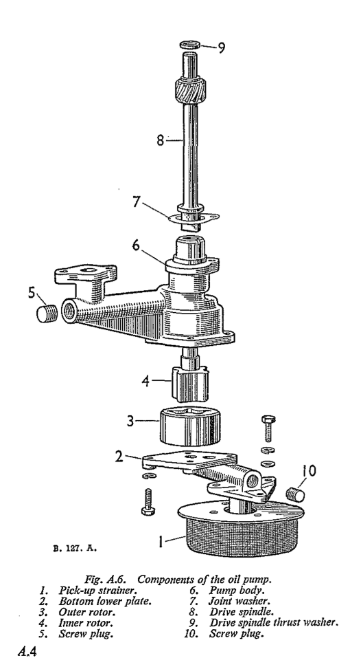
OIL PUMP
Removing the Oil Pump
- Remove the sump and pick up strainer.
- Take off the nuts and spring washers from the three studs which secure the oil pump assembly to the crankcase, when the pump can be withdrawn. If the pump is removed with the engine still in the car, the drive shaft will be free to disengage from the camshaft, and care must be taken to prevent it falling out. Note also the thrust washer fitted on the drive shaft above the gear
Dismantling the Oil Pump
Mark the flange and pump body to assist reassembly. Separate the body from the bottom flange. The outer rotor can then be lifted out of the body.
Replacing the Oil Pump
Insert the pump from below and push the shaft right home until the driving gear is meshed with the gear on the camshaft.
Section A.9
RELIEF VALVE
The non-adjustable oil pressure relief valve is situated at the rear of the right-hand side of the cylinder block below the oil filter and is held in position by a hexagon nut sealed by a copper washer. The relief valve spring retains a valve cup against a seating machined in the block.
Section A.10
VALVE ROCKER SHAFT
The valve rocker shaft on the cylinder head is hollow. It is supplied with oil by a pipe connection and is drilled for lubrication to each rocker bearing.
This shaft is plugged at each end, one of these being screwed in order that the shaft may be cleaned internally.
Section A.11
ADJUSTING VALVE CLEARANCE
Lift off the valve cover after removing the two flat and two dome cap nuts.
Between the rocker arm and the valve stem there must be a clearance of .012 in. (.305 mm) for both inlet and exhaust, clearance being set with the engine hot.
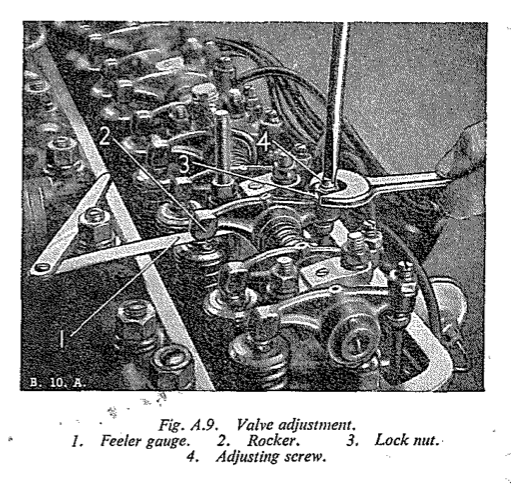
- If adjustment is necessary, slacken the locknut whilst continuously applying sufficient pressure to the adjusting screw with a heavy screwdriver, and raise or lower the adjusting screw in the rocker arm. Check the clearance with a feeler gauge.
- Tighten the locknut when the adjustment is correct, but always check it again afterwards in case the adjustment has been disturbed during the locking process.
- When replacing the valve cover, lake care that the joint washer (using a new one if necessary) is properly in place to ensure an oil tight joint.
Section A.12
ROCKER SHAFT ASSEMBLY
Removal
- Disconnect the breather pipes at their rocker cover terminals.
- Unscrew the two flat and two dome nuts securing the rocker cover to the cylinder head, taking care not to damage the cork gasket, and remove the rocker cover.
- Detach the oil feed pipe at the union on the cylinder head.
- Unscrew and remove the twelve nuts and spring washers which old the rocker shaft brackets to the cylinder head. (5. Remove the rocker assembly, complete with brackets, rockers and oil feed pipe.
Dismantling
- Unscrew and remove the oil feed pipe banjo from its bracket noting its corresponding position on the shaft.
- Remove the split pins from the end of the rocker shaft to release thrust washers and double coil springs.
- Withdraw rocker, rocker shaft brackets, thrust washers and springs, retaining them in their original order for reassembly.
Reassembling
When reassembling the rocker gear, commence with No. 4 bracket and secure the oil feed pipe with the washers in position, ensuring that the dowel on the banjo bolt locates in the rocker shaft.
The brackets are fitted with the highest lug to the camshaft side of the engine, and the rocker shaft is fitted with the screwed in end plug to the front. The rear end tapered plug is a drive fit.
A thrust washer is fitted each side of each rocker shaft bracket, and all springs, and rockers, and the remaining brackets are interchangeable.
Section A.13
PUSH ROD REMOVAL
If the valve rocker assembly has already been removed all that remains is for the push rods to be lifted out. They may on the other hand be taken out without detaching the rocker assembly as described below :-
- Remove the valve rocker cover as described in Section A.12 and slacken the valve adjustment screw to its full extent.
- With the aid of a screwdriver supported under the rocker shaft, depress the valve and slide the rocker sideways free of the push rod.
- Withdraw the push rod. When reassembling the rocker gear, commence with
- In the case of the rocker at each end, it is necessary to take out the split pins at the end of the shaft.
- The above sequence should be reversed when replacing push rods and rockers.
Section A.14
ROCKER ARM BUSHES
- While the rocker gear is detached from the head, check for play between the rocker shaft and the rocker arm bushes. If this is excessive new bushes should be fitted. To do this dismantle the rocker assembly as described in Section A.12.
- The bush is best removed by using a drift and anvil (Service Tool No. 18G 21). The anvil is recessed to retain the rocker in position while the bush is gently knocked out by the drift. File and drill out the rivet in the rocker arm oilway.
- The flange of the drift is also recessed to prevent the new split bush from opening when being driven into position with the joint immediately above the rocker arm oilway
- Drill an oilway through the bush from the top of the rocker using a .0785 in. diameter drill. A second oilway must be drilled through the bush via the rocker arm using a .089 in. diameter drill.
- Plug the oilway in the rocker arm with a rivet and weld its head to the rocker boss. Reamer the internal diameter of the bush to suit the shaft
Section A.15
TAPPETS
Removal
- Remove the valve rocker shaft assembly as detailed in Section A.12.
- Disconnect the dynamo terminals and remove the set bolt securing the dynamo to the slotted link. Take out the bolts on which the dynamo pivots and remove the dynamo and coil.
- Release the front tappet chamber cover by removing the five securing bolts. The centre and rear tappet chamber covers give access to the valves for No. 3, 4, 5 and 6 cylinders when the single retaining bolts are removed.
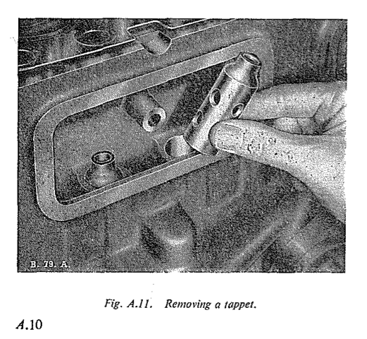
- Withdraw the push rods, keeping them in their respective positions to ensure replacement onto the same tappets. Lift out the tappets, keeping them in the same respective locations. Inspect the tappet cam contacting surfaces for wear. New tappets should be fitted by selective assembly so that they just fall into their guides under their own weight when lubricated.
Replacement
Assembly is a reversal of the above procedure, but care should be taken to see that the tapper cover joints are oil tight and that the rockers are adjusted to give the correct valve clearance.
Section A.16
RENEWING VALVE SPRING IN POSITION
- In an emergency a new valve spring(s) can be the fitted without lifting the cylinder head, but it is advisable first to bring the piston to top dead centre, to ensure that the valve cannot fall into the cylinder during the process.
- Remove the sparking plug, and by means of a length of copper tubing or similar tool inserted through the plug hole, the valve can be held on its seat whilst the spring is compressed. The valve rocker shaft can be used as a fulcrum point by an operator using two screwdrivers to bear on the valve spring cap each side of the valve stem, whilst the cotters are removed.
Section A.17
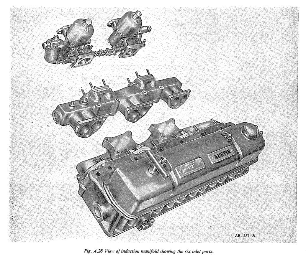
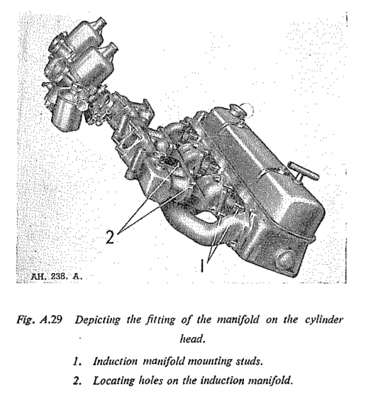
MANIFOLD
Removal and Replacement
- Detach the air cleaners from the carburetters by unscrewing the four setpins and releasing the breather pipe attached to the air cleaner.
- Disconnect the heat shield by removing the two securing nuts and washers.
- Unscrew and remove the six brass nuts and plain washers which secure the exhaust manifold to the down pipes.
- Disconnect the throttle and choke linkages to the carburetters, together with the vacuum control pipe and petrol feed pipe.
- Unscrew and remove the 14 nuts and washers which secure the exhaust manifold and carburetters to the cylinder head (four on the carburetter flanges, ten on the exhaust manifold). This will automatically release the heater outlet pipe.
- The exhaust manifold and carburetters can then drawn off their respective studs and lifted clear of the engine.
- Reassembly is the reverse of the above procedure; always use a new joint washer for the exhaust manifold to ensure an air tight joint.
Section A.18
CYLINDER HEAD
Removing
- Drain all water from the cooling system, if the water contains anti-freeze mixture, it should be run into a clean container and used again.
- Detach the top water hose from the cylinder head.
- Disconnect the high tension wires from the sparking plugs and remove the plugs.
- Detach the exhaust manifold, complete with carburetters, as detailed in Section A.17.
- Remove rocker cover and breather pipes as described in Section A.12.
- Release the suction advance pipe clip from its securing point on the cylinder head. Also slacken the retaining clip and detach the heater inlet hose.
- Remove the rocker assembly as described in Section A.12.
- Withdraw the push rods, keeping them in order of removal taking care not to pull the tappets out of their guides in the block.
- Remove the sixteen cylinder head nuts together with their flat washers and lift off the cylinder - head.
Replacing
- Replace the cylinder head joint washer with the side marked
Top
uppermost, it is not necessary to use jointing compound or grease for the gasket. - Having slipped the gasket over the studs, next lower the cylinder head into position and position the cylinder head stud nut washers. Ensure that a bronze washer is fitted below the steel washer on each stud which passes through the inlet manifold on the left-hand side of the head; also ensure that the suction advance pipe clip is replaced in its original position on the cylinder head.
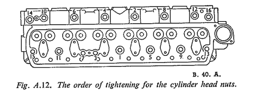
- Fit the nuts finger tight and then tighten them a turn at a time, in the order given in fig A.12, to the recommended torque spanner readings.
- Insert the push rods, ensuring that the ball ends - are correctly located in the tappets.
- Replace the rocker gear and connect the oil feed, as described in Section A.12.
- Reset the valve clearance, and replace the rocker cover using a new joint washer if the old one is damaged in any way.
- Replace the exhaust manifold and carburetters and connect up the petrol pipe, throttle and choke controls and heater outlet pipe. Tighten the manifold nuts evenly ensuring that a good joint is made.
- Reconnect heater inlet pipe, water hose from the thermostat housing to the radiator, and breather pipes.
- Refill the cooling system, replace plugs and their washers, and the wires to their respective plugs.
- Check the valve clearance again after the vehicle has run about 100 miles (160 km.) as the valves have a tendency to bed down. At the same time it is advisable to test the cylinder head nuts for tightness. By using the special cylinder head nut spanner (Service Tool 18G 545) it is possible to perform this operation without removing the rocker shaft assembly. Tightening the cylinder head nuts may affect valve clearances, although not usually enough to justify resetting.
Section A.19
REMOVING AND REFITTING VALVES
With the cylinder head removed, a valve lifting tool can be used to compress the springs (Service Tool No. 18G 106). Take away the circlip, split cotters, and valve stem cap, so releasing the springs and allowing the valve to be removed.
- When removing the valves, place them in a rack, thus enabling them to be paired up with their correct cylinders. The valve springs should be tested and their free length checked, the correct length being approx. 1.969 in. (50.03 mm.) for the inner spring and 2.047 in. (52 mm.) for the outer spring.
- Clean the carbon from the top and bottom of the valve heads, as well as any deposit that may have accumulated on the stems. The valve heads should, if necessary, be refaced at an angle of
45º for the exhaust valve and 30º for the inlet valve. If the valve seats show signs of excessive pitting it is advisable to reface these also.
- The valves are made without any indentures or slots in the head, this necessitates the use of a rubber suction valve grinding tool.
- Reassembly is a reversal of the operations for removal.
Section A.20
VALVE GRINDING
- For valve grinding a little grinding paste should be smeared evenly on the valve face, and the valve rotated backwards and forwards against its seat (using Service Tool No. 18G 29), advancing it a step at short intervals until a clean and unpitted seating is obtained. The cutting action is facilitated by allowing a light spring situated under the valve head, to periodically lift the valve from its seat. This allows the grinding compound to re-penetrate between the two faces after being squeezed out.
- On completion, all traces of compound must be removed from the valve and seating. It is essential that each valve is ground-in and refitted to its own seating.
- It is also desirable to clean the valve guides; this can be done by dipping the valve stem in petrol or paraffin, and moving it up and down in the guide until it is free.
Section A.21
VALVE GUIDES
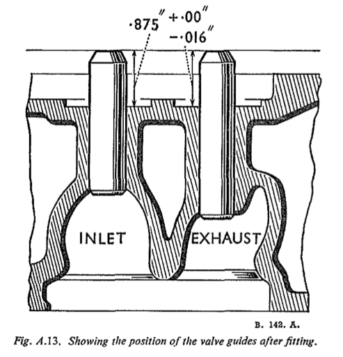
- The valve guides are of a one-piece design. They are pressed into the cylinder head to allow .859 to .875 in. (21.8 to 22.23 mm.) of the guide to protrude above the machined face when fitted.
- To position each valve spring on the cylinder head, a stepped pressed steel seating collar is fitted over the part of the guide protruding from the cylinder head.
- Valve guides should be tested for wear whenever valves are removed, and if excessive side play is present, a close check should be made of the valve stem and the guide. In the event of wear being noticeable, the defective components should be renewed. If a valve is at fault the wear will be evident on the stem. It should be borne in mind that the valve stem and guide should be a running fit to avoid the possibility of an air leak.
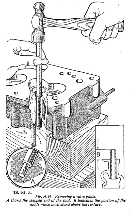
- If renewal is necessary due to wear, the valve guide may be driven out after removal of the valve, as shown in fig A.14.
- The drift is stepped from a ½in. (12.7 mm.) diameter to a 5/16 in. (7.9 mm.) diameter locating spigot in order to obviate it slipping off the guide and damaging the port. Knock out the guide in the direction shown.
- A new guide should be driven into position in the same direction, that is, inserting it through the valve seating and driving towards the top of the cylinder head.
- The final position of the guide is shown in fig A.13.
Section A.22
DECARBONISING
- Remove the cylinder head as described in Section A.18.
- Scrape off all carbon deposit from the cylinder head and ports. Clean the carbon from the piston crowns, care being taken not to damage the pistons, and not to allow dirt or carbon deposit to enter the cylinder barrels or push rod compartment. When cleaning the top of the pistons do not scrape right to the edge as a little carbon left on the chamfer assists in keeping down oil consumption; with the pistons cleaned right to the edge or new pistons, oil consumption is often slightly though temporarily increased.
- Blow out the oil passages and swill out the water passages using a water hose. The gasket contacting - surfaces of the head should be checked for flatness with a straight-edge and the surfaces examined for scores. If the cylinder head is found to be badly out of true it should be renewed.
- Remove all carbon accumulation from the valves and thoroughly clean them. Inspect the valve bases and seats and if they are slightly pitted or rough, grind them in, as described in Section A.20. If the valves and seats show signs of excessive pitting, or the faces are not flat, the valves and seats should be replaced.
- Examine the valve guides, as described in Section A.21.
- Broken or weak valve springs should be renewed. The other valve springs should be tested and the results compared with figures given under
General Data
. - Clean the rocker shaft gear and blow out the oil passages as described in Section A.10.
- Inspect the rocker shaft, rockers and bushes for wear. Renew any worn rocker bushes as described in Section A.14.
- Reassemble and install the cylinder head assembly
The following operations should be carried out with the engine removed, although in some cases it is possible to perform them with the engine in position.
Before removing or replacing any component it is important to ensure that all surrounding surfaces are perfectly clean, to prevent the entry of foreign matter into the engine. This can best be accomplished by the use of a paraffin bath and brush, and it is also important to note that fluffy rags should never be used, as there is danger of causing obstruction to small oil ways.
Section A.23
CONNECTING RODS AND BEARINGS
Removal
- Remove the cylinder head assembly as described in Section A.18.
- Drain and remove the sump (see Section A.5).
- Remove the self-locking nuts securing the caps and bearings to the connecting rods. Remove the caps and bearings.
- Withdraw the pistons and connecting rods upwards through the cylinder bores.
- It may be necessary to remove the carbon or ridge from the top of the bores prior to pushing the pistons upwards, to avoid piston-ring fracture.
- Remove the pistons from the connecting rods by unscrewing the clamp bolt from the small end of the connecting rod and pushing the gudgeon pin out.
- Ensure that each connecting rod, cap and bearing is marked with the cylinder number from which it was removed.
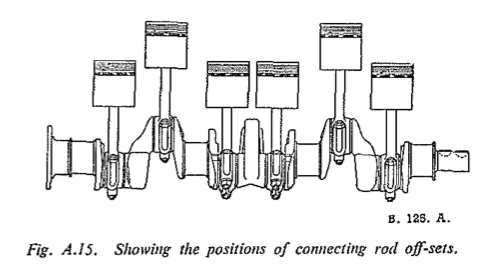
- The big ends are offset, and rods in numbers 1, 3 and 5 cylinders are offset towards the front, with 2, 4 and 6 cylinders offset towards the rear.
- The alignment of the connecting rods should be checked on an alignment fixture. On no account must the rods or caps be filed.
- Examine the bearing shells for wear and pits. Renew the bearing shell if necessary. Bearings are pre-finished with the correct diametrical clearance and do not require bedding in.
- Check the crankpins with a micrometer if they are worn oval or are scored, the crankshaft will have to be removed for regrinding, see Section A.29.
Replacing
Before installing the connecting rods and bearings it is assumed that the pistons and rings have been serviced, see Section A.24.
The pistons and connecting rods must be fitted in the same cylinder bores and the same way round as when removed.
- Assemble the piston and the connecting rod to the gudgeon pin, so that the split in the piston skirt is adjacent to the split in the top of the connecting rod.
- Refit the piston rings very carefully, make quite sure that the pistons and bores are perfectly clean and smear the bores with clean engine oil.
- Use a piston ring clamp, service tool No. 18G 55A, when replacing the pistons from the top of the bore, and make sure that the split in the piston faces away from the camshaft.
- Clean the crankpins and both sides of the shell bearings, locate the feathered ends in the connecting rod and its cap, and smear the crankpins with engine oil.
- Before fitting the cap, check that the number stamped on the rod is the same as that on the cap. Note that the recesses in the cap and rod must be on the same side. Tighten the nuts. Turn the crankshaft after fitting each rod, to ensure that the bearing is not binding on the crankpin. Also check the side clearance of each rod, as given under
General Data
. - Refit the cylinder head assembly, see Section A.18.
- Refit the sump and refill with recommended grade of oil, see Section Q.
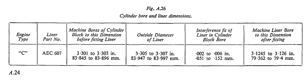
Section A.24
PISTONS, RINGS AND GUDGEON PINS
Removal
The split-skirt pistons are of aluminium alloy material. Four rings are fitted above the gudgeon pin, the bottom ring being of the oil-control type. The pistons are fastened to the connecting rods by gudgeon pins which are clamped rigidly in the small ends of the connecting rods. Bushings are not needed in the gudgeon pin bosses of the pistons because the aluminium alloy material serves as a suitable bearing for the gudgeon pins, the bearing surfaces of which are lubricated by means of splash through the two holes drilled in each boss. To remove the pistons see Section A.23.
To view and overhaul
- Remove the rings over the tops of the pistons.
- Scrape all accumulation of carbon off the piston heads and, using a piston ring groove-cleaning tool or an old ring section, carefully scrape all carbon out of the ring grooves of the pistons. Clean the carbon out of the oil holes in the piston ring grooves.
- Thoroughly clean all the dismantled components in paraffin.
- Examine all parts for wear and damage, renew if necessary.
- If cylinder reconditioning is required (see Section A.30), determine the amount of material to be removed (refer to
General Data
concerning oversize pistons available).
- When fitting new or oversize pistons and rings to piston. The fit can be checked after the rod has reconditioned cylinder bores, the clearances should be controlled within the limits given under
General Data
. Selective assembly is necessary, and for this purpose pistons are stamped with distinguishing symbols of grade and oversize. - Piston rings should have a gap clearance (see
General Data
) when installed in the cylinder bores. If new rings are being installed, each
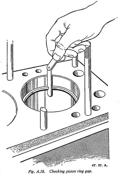
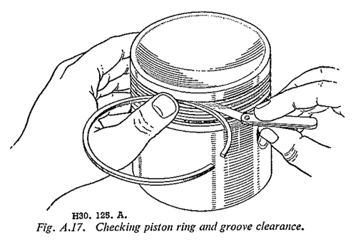
ring should be checked in the cylinder bore to determine whether its gap clearance is within the range specified. To do this, use the bottom of a piston to insert the ring part way into the bore. The ring will be squared up in the bore to measure the gap clearance as shown in fig A.18. To check the ring clearance in the piston grooves, install the rings on the pistons and determine the clearances with a feeler gauge. If the piston ring grooves are worn excessively, as indicated when comparing the actual clearances with those given under General Data
, renew the rings and pistons.
- Gudgeon pins should be a hand-push fit in the piston. The fit can be checked after the rod has
been assembled by holding the piston with the connecting rod in an approximately horizontal position. The weight of the large end of the connecting rod should be just insufficient to turn the gudgeon pin in the piston. On no account must gudgeon pin piston bosses be reamed out as oversize gudgeon pins are not supplied or permitted.
Replacement
Section A.25
TIMING CHAIN AND WHEELS
Removal
- Remove the radiator as described in Section C, if the removal is to be done with the engine in position.
- Slacken the generator fixing bolts and take off the fan belt. Unscrew the starter dog nut using Service Tool No. 18G 391. Before doing this the tab washer must be knocked back.
- In some cases it may now be possible to remove the crankshaft damper and pulley complete as one unit. If, however, the pulley is tight on the crankshaft, it will be necessary to undo the six nuts securing the damper, and with this component removed, draw off the pulley with Service Tool No. 18G 2.
- Take out the five ¼in. and the seven 5/16 in. setpins from the timing cover flange, taking care to retrieve the special elongated washers fitted under the heads. The cover can now be removed and joint washer separated, taking care to remove and retain the oil thrower.
- Remove the automatic chain tensioner, see Section A.26.
- Unlock and remove the camshaft chain wheel nut and remove the nut and lockwasher. Note that the locating tag on the lockwasher fits into the keyway of the camshaft chain wheel.
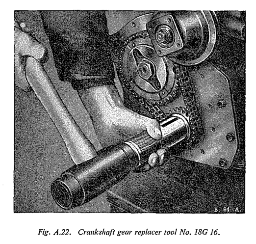
- The camshaft and crankshaft chain wheels may now be removed, together with the timing chain, by easing each wheel forward a fraction at a time with suitable small levers or Service Tool No. 18G 58. As the crankshaft gear wheel is with- drawn care must be taken not to lose the gear packing washers immediately behind it.
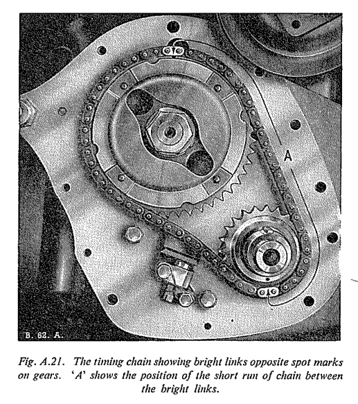
Ashows the position of the short run of chain between the bright links
- Clean and examine the joint faces of the timing cover and the front mounting plate.
- Examine the felt oil seal for signs of wear, hardening or damage. If the slightest wear or damage is apparent the timing cover and seal must be renewed as an assembly.
- Inspect chain wheels for worn, broken or chipped teeth.
- Inspect the timing chain for excessive wear or stretch.
- Examine the timing chain tensioner, see Section A.26.
Reassembling
The installation of the timing chain and wheels is the reversal of the removal procedure but for the following points :-
- Replace the same number of washers as was found when dismantling, unless new camshaft or crankshaft components have been fitted, which will disturb the alignment of the two gear wheels. To determine the thickness of washers required, place a straight-edge across the sides of the camshaft wheel teeth and measure with a feeler gauge the gap between the straight-edge and the crankshaft gear.
- When replacing the timing chain and gears, set the crankshaft and camshaft with the keyways approximately at T.D.C. when seen from the front. Double the timing chain, bringing both bright links together. This gives a long and short portion of the chain on either side of the bright links. With the shorter part of the chain on the Right, (the bright links facing the operator), and the longer on the Left, engage the marked camshaft sprocket tooth with the top bright link, and the crankshaft sprocket with the marked tooth coinciding with the other bright link. Place the sprockets in their respective positions on the camshaft and crankshaft, complete with the chain, and push the assembly home. Carefully keep the sprockets in line with each other all the time to avoid straining the chain. When replaced on the engine, the bright links and the marked teeth should take up the position shown in fig A.21.
- Replace the camshaft chain wheel locking washer and nut.
- Apply engine oil to the timing chain and wheels before installing the cover.
- Replace the oil thrower, concave side towards the front of the engine.
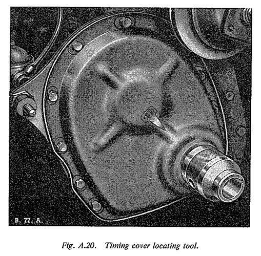
- Use camshaft pulley boss, or Service Tool No. 18G 3 to locate the timing cover felt washer before the timing cover flange bolts are tightened. NOTE: A new joint washer should be fitted between the timing cover and the front mounting plate.
Section A.26
AUTOMATIC CHAIN TENSIONER
Description
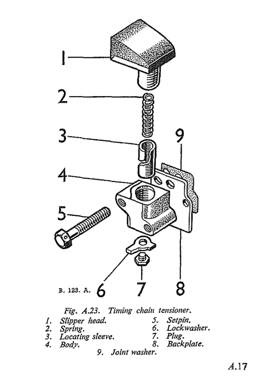
The timing chain tensioner is secured to the engine front mounting plate by two bolts and a locking plate. When the tensioner is in operation and the engine is running, oil from the lubrication system enters the spigot on the back face under pressure and lubricates the bearing surface through a hole in the tensioner slipper pad.
The tensioner consists of a cylinder with a helical slot which moves in a plunger by the action of a compressed spring in the tensioner body. The helical slot has a recessed lower edge. Should the chain wear through use, the spring pushes the plunger and pad outwards against the chain. A limiting peg in the plunger, bearing on the upper edge of the helical slot, rotates the cylinder until the next recess in the lower edge engages it, and the plunger is prevented from returning to its original position and allowing the chain to become slack.
To Remove
- Unlock the tab washer fitted to the tensioner bottom plug and remove the plug from the body.
- Insert a 1/8 in. (3 mm.) Allen key into the plug hole to engage the cylinder, and turn the key in a clockwise direction (viewed from the opposite end to the slipper), until the rubber slipper is completely free of spring pressure. Between a half and one full turn is necessary.
- Unlock and remove the bolts to release the chain tensioner assembly and back plate.
To Dismantle
- Withdraw the plunger and slipper assembly from the tensioner body and engage the lower end of the cylinder with the Allen key.
- Turn the key in an anti-clockwise direction, gripping the plunger and key securely, until the cylinder and spring are released from inside the plunger.
To Inspect
- Clean the components thoroughly in petrol.
- The oil hole in the spigot, and outlet oil hole in the slipper should be blown out by compressed air before reassembly.
- Check the tensioner spring and examine the slipper pad for wear. Renew as necessary. (See Section A.37.)
To Reassemble
- Insert the spring in the plunger and place the cylinder on the other end of the spring.
- Compress the spring until the cylinder enters the plunger bore and engages with the peg in the bore.
- Hold the assembly compressed in this position and engage the Allen key. Turn the cylinder in a clockwise direction until the end of the cylinder is below the peg, thus fully compressing the spring and locking cylinder.
- Withdraw the key and insert the plunger assembly into the body.
To Replace
- Position the back plate and secure the assembly to the cylinder block.
- Move the timing chain into position and release the tensioner for operation by inserting the Allen key and turning it in an anti-clockwise direction as far as possible, assisting the slipper to rise initially with the finger.
- Secure the bolts into their locking plate, replace the bottom plug, and lock it with a tab washer.
Section A.27
CAMSHAFT AND BEARINGS
Removal
- Drain the sump and release it from the engine. Remove the oil pump, and then take off the rocker assembly, see Sections A.7, A.8 and A.12.
- Remove the push rods and take out the tappets, see Section A.13.
- Remove the timing cover, timing chain tensioner, chain and gears, see Sections A.24 and A.25.
- Remove the distributor and spindle drive, see Section B. Do not slacken the clamping plate bolt or the ignition timing setting will be lost.
- Take out the two setscrews which secure the camshaft locating plate to the cylinder block.
- Withdraw the camshaft forward rotating it slowly to assist the withdrawal.
- Inspect the camshaft bearing journals and cams for signs of scoring. If the journals are not within the required diameter limits (see under
General Data
), the camshaft should be renewed. - Examine the camshaft bearings for scores, pits or evidence of failure. If the bearings have to be renewed it will necessitate the removal of the engine back plate as described in Section A.29. The old bearings can than be withdrawn and new ones installed, using Service Tools 18G 124A. 18G 124C, 18G 124D, 18G 124E, 18G 124F, 18G 124H, 18G 124L.
Oil holes must be lined up carefully and all bearings reamed in line to give .001 to .002 in. (.025 to .051 mm.) clearance in each, using Service Tools 18G 123A, 18G 123C, 18G 123D, 18G 123E, 18G 123F, 18G 123AB, 18G 123R, 18G 123T, 18G 123AA, 18G 123L.
- Inspect the tappet cam contacting surfaces for wear. New tappets should be installed wherever evidence of unusual wear is found.
- The installation of the camshaft and tappets is a reversal of the procedure
Removal
. Lubricate the camshaft journals with engine oil.
Section A.28
FLYWHEEL AND ENGINE REAR PLATE
To Remove
The flywheel complete with starter ring is secured to the flange on the rear of the crankshaft by four set bolts, which are locked in position by three lockplates. The engine rear plate is secured to the crankcase by set bolts and lockwashers. To remove the flywheel and rear plate, after the engine is removed from the vehicle, proceed as follows :-
- Remove the gearbox from the engine (see Section F
- Remove the clutch (see Section E.
- Knock back the tabs of the lockplates, unscrew the bolts and withdraw the flywheel.
- Unscrew the set bolts and withdraw the engine rear plate. Note the cork sealing strip behind the engine rear plate under the crankshaft flange.
- Examine the flywheel teeth and friction face for excessive wear. If the teeth on the starter ring are damaged or badly worn, a replacement flywheel and ring may be fitted. NOTE : For instructions on fitting a flywheel starter ring only see Section A.32.
- Examine the engine rear plate for distortion and damage and clean the joint faces of the plate and crankcase and check for scores.
To Install
- Refit the engine rear plate to the crankcase, using a new joint washer. Tighten the securing bolts evenly and firmly.
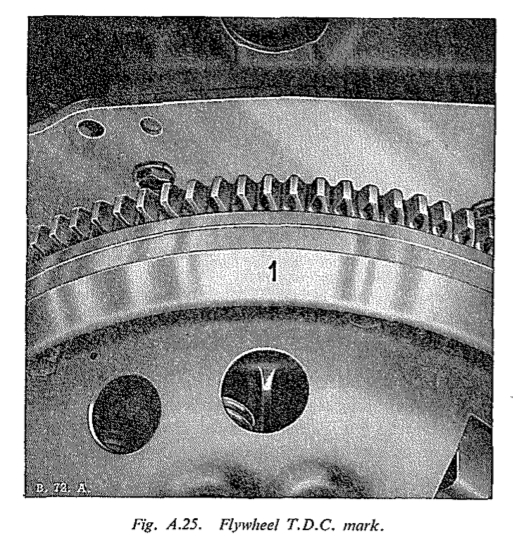
- Place the flywheel over the flange and flange bolts of the crankshaft so that the timing mark
1
is at T.D.C. when the first throw of the crankshaft is at T.D.C. The joint faces should be perfectly clean. Fit the lockplates and nuts on the bolts and tighten them in diagonal sequence.
Section A.29
CRANKSHAFT AND MAIN BEARINGS
To Remove
The forged-steel crankshaft is statically and dynamically balanced and is supported in the crankcase by three renewable main bearings of the sintered copper and lead steel-backed type. Crankshaft end float is controlled by thrust washers fitted on both sides of the centre main bearing.
- Remove the engine from the vehicle (see Section A.4 and place it upside-down in a dismantling fixture.
- Remove the sump and oil strainer (see Section A.7.
- Remove the timing chain (see Section A.25.
- Remove the flywheel and engine rear plate (see Section A.28
- Check the crankshaft end float to determine whether the renewal of the thrust washers is necessary.
- Remove the connecting rod bearing caps and shells, keeping the shells with their respective caps for correct replacement, and release the connecting rods from the crankshaft. Remove the sparking plugs from the cylinder head to facilitate the turning of the crankshaft.
- Withdraw the main bearing caps complete with bearing bottom shells. Caps and both bearing half-shells should be kept together. The use of Service Tool 18G 42 and adaptor 18G 42B will assist in the removal of the
- bearing caps. Remove the screwed plug from the rear bearing cap oil return pipe and withdraw the pipe in order to use the extractor. Note that each main bearing is stamped with a common number, which is also stamped on the centre web of the crankcase near the main bearing. The bottom halves of the two thrust washers will be removed with the centre main bearing cap.
- Remove the crankshaft, the two remaining halves of the thrust washers and the top half-shells of the main bearings from the crankcase.
- Inspect the crankshaft main journals and crankpins for wear, scores, scratches and ovality. If necessary the crankshaft may be re-ground to the minimum limits shown under
General Data
. Main bearings for re-ground crankshafts are available in sizes shown underGeneral Data
. - Clean the crankshaft thoroughly, ensuring that the connecting oilways between the journals and crankpins are perfectly clear. They can be cleaned out by applying a pressure gun containing petrol or paraffin. When clean, inject a thin oil in the same manner.
- Thoroughly clean the bearing shells, caps and housings above the crankshaft.
- Examine the bearing shells for wear and pitting, and look for evidence of breaking away or picking-up. Renew the shells if necessary.
- Bearings are pre-finished with the correct diametrical clearance, and do not require bedding in. New bearings should be marked to match up with the marking on the cap, and on no account should they be filed to take up wear or to reduce running clearance.
- Check the thrust washers for wear on their bearing surfaces, and renew if necessary to obtain the correct end Boat.
To Install
The installation of the crankshaft and main bearings is a reversal of the procedure To Remove
, noting the following points :-
- Ensure that the thrust washers are replaced the correct way round and locate the bottom half tab in the slot in the bearing cap.
- The bearing shells are notched to fit the recesses machined in the housing and cap.
- In the case of the front and rear main bearing caps, install new cork or felt sealing strips.
- The rear main bearing cap horizontal joint surfaces should be thoroughly cleaned and lightly covered with WEL-SEAL (manufactured by Messrs. Wellworthy Ltd.) sealing compound before the cap is fitted to the cylinder block. This will ensure a perfect oil seal when the cap is bolted down to the block.
- Lubricate the bearings freely with engine oil.
- Tighten the main bearing nuts, see
General Data
for torque spanner settings.
Section A.30
CYLINDER BLOCK
To Remove and Dismantle
- Remove and dismantle the engine (see Section A.4).
- Remove all studs, unions and screwed plugs, etc., if necessary.
- If an expansion plug has blown, or leaks, remove the plug by drilling a hole in its centre and lever it out with a screwdriver or other suitable tool.
To View and Overhaul
- Scrape as much sediment as possible from the water passages and thoroughly swill out with a water hose.
- Clean all gasket surfaces.
- Inspect for cracks and scores on gasket surfaces.
- It may be advisable to remove the ridge above the ring travel at the top of the cylinder bores before checking the fit of the pistons.
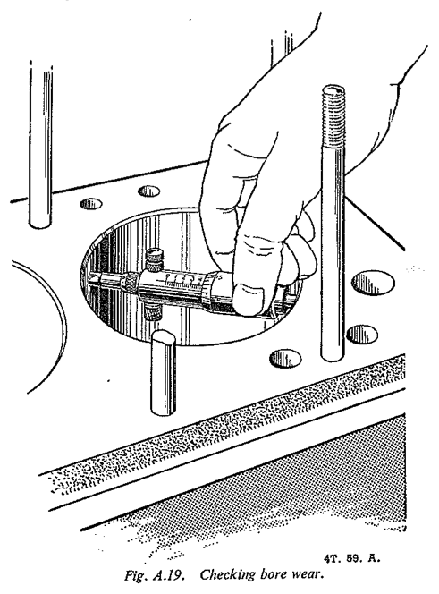
- Wipe the cylinder bores clean and examine them for scores, out-of-round and taper. If the cylinders are found to be out-of-round or excessively tapered when measured with a dial test indicator, they should be reconditioned.
- If cylinder reconditioning is required, determine accurately the amount of material to be removed (refer to
General Data
concerning oversize pistons available). - Make sure that all traces of abrasives are cleaned from all parts of the cylinder block after the cylinder reconditioning operation is completed.
- Check the camshaft bearings (see Section A.27).
To Reassemble and Install
- Install all studs, unions and screwed plugs, etc.
- When installing new expansion plugs, coat the edge of the plug with a sealing compound and insert the plug with the
bulge
on the outside. A carefully aimed blow at the centre of the plug with a small hammer direct or with a blunt punch will expand the plug sufficiently to make a watertight joint. If too heavy a blow is used, the plug will be useless and must be replaced by another new one. - Reassemble, install and test the engine (see Section A.4).