Section D.1
THE FUEL TANK
- Remove the drain plug from the tank and drain the petrol into a suitable receptacle.
- Within the luggage compartment release and remove the spare wheel by disconnecting its securing strap.
- Remove the carpet which covers the floor of the luggage compartment.
- Remove the petrol tank feed pipe cover, situated in the top right-hand corner of the boot, by unscrewing the six securing Phillip screws. Disconnect the feed pipe from the tank.
- Disconnect the petrol tank filler pipe at its union with the tank. The union is made by a rubber joint hose and two securing clips.
- Detach the insulated lead from the petrol gauge unit terminal.
- Release the tank securing straps by unscrewing the nut and locknut of each tank strap stud, These nuts are visible on the underside of the luggage compartment floor just in front of the rear body panel. Pull the straps through the compartment floor and hinge them back on their clevis pin anchorages.
- Lift out the tank.
Section D.2
FUEL PUMP
Description
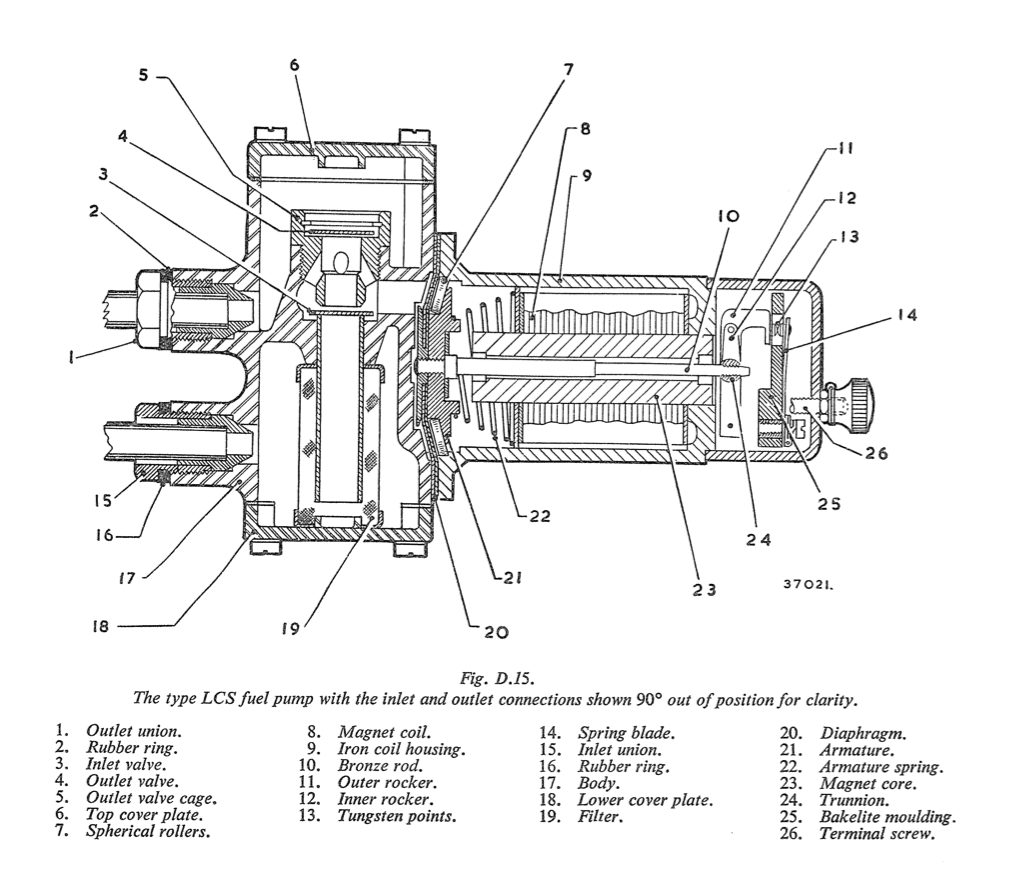
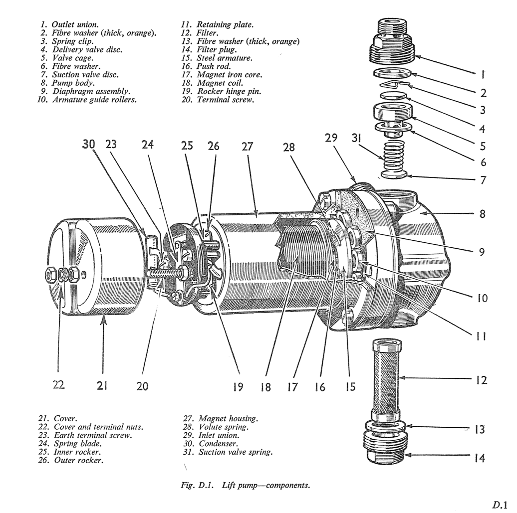
The fuel pump is an S.U. type H.P., 12-volt electric pump. (See Fig. D.1). The pump consists of three main assemblies, the body, the magnet assembly and the contact breaker. The body is composed of a hollow alloy die-casting (8) in two parts, into the bottom of which the filter (12) is screwed. The pump inlet union (29) is screwed in at an angle on one side. The outlet union (1) is screwed into the top and tightens down on the delivery valve cage (5)which is clamped between the two fibre washers (2) and (6). In the top of the delivery cage is the delivery valve, a thin brass disc (4) held in position by a spring clip (3). Inserted in the bottom of the cage is the suction valhe (7), being a similar disc to (4) and held lightly on a seating machined in the body by a spring. Holes connect the space between the valves and the pumping chamber, a shallow depression on the forward face of the body. This space is closed by a diaphragm assembly (9) clamped at its outside edge between the magnet housing (27) and body (8) and at its centre between the retaining plate and the steel armature (15). A bronze rod to which the diaphragm is attached (16) is screwed through the centre of the armature, passes through the magnet core to the contact breaker, located at the other end. A volute spring (28) is interposed between the armature and the end plate of the coil to return the armature and diaphragm. The magnet housing consists of a cast-iron pot containing an iron core (17), wound with a coil of copper wire to energise the magnet. Between the magnet housing and the armature are fitted eleven spherical- edged brass rollers (10). These locate the armature centrally within the magnet at all times, and allow absolute freedom of movement in a longitudinal direction. The contact breaker consists of a small bakelite moulding carrying two rockers (25) and (26), which are both hinged to the moulding at one end and are connected together at the top end by two small springs, arranged to give a throw over
action. A trunnion is fitted into the centre of the inner rocker, and the bronze push-rod (16) connected to the armature is screwed into this. The outer rocker (26) is fitted with a tungsten point, which makes contact with a further tungsten point on a spring blade (24). This spring blade is connected to one end of the coil, and the other end of the coil is connected to the terminal (20). A short length of flexible wire is connected to the outer rocker and to the other terminal (23) which also serves to hold the bakelite moulding on the magnet housing.
The rocker mechanism is insulated by fibre bushes Two fibre bushes are fitted to one of the spindles of the ’’throw over" mechanism in order to silence the operation of the contact breaker.
Action of the Fuel Pump
When the pump is at rest, the outer rocker lies in the outer position and the tungsten points are in contact. The current passes from the terminal through the coif back to the blade, through the points and to the earth return, thus energising the magnet and attracting the armature. This comes forward, bringing the diaphragm with it and sucking petrol (gasoline) through the suction valve into the pumping chamber. When the armature has advanced nearly to the end of its stroke the throw over
mechanism operates, and the outer rocker flies back, separating the points and breaking the circuit. The spring (28) then puslies the armature and diaphragm back, forcing petrol (gasoline) through the delivery valve at a rate determined by the requirements of the engine. As soon as the armature gets near the end of this stroke the throw over
mechanism again operates, the points again make contact, and the cycle of operations is repeated.
Section D.3
SERVICING THE PUMP
When a pump comes in for reconditioning, the first thing to do is to determine, by the sense of smell, whether the parts in contact with the fuel have become coated with gum. The gum is a substance similar to varnish and can cause the eventual destruction of the diaphragm. Its presence can be detected by smelling the outlet union: if an unpleasant stale smell is noticed, gum is present. The ordinary smell of petrol (gasoline) i denotes that no gum has been formed.
To Dismantle the Pump
- Unscrew the filter plug and remove the plug, washer and filter. The latter may be found clogged with gum.
- Remove the inlet union and washer.
- Remove the outlet union and its washer.
- Extract the valve cage, valve cage washer, suction valve and spring. Remove the circlip retaining the delivery valve and withdraw the valve disc.
- Unscrew the six screws holding the two main components of the pump together. If the presence of gum has been detected, all parts (NOT ALUMINIUM) must be boiled in 20 per cent. caustic soda solution, dipped in nitric acid and then washed in boiling water. Aluminium parts must be cleaned by thoroughly soaking in methylated spirits.
- If no evidence of gum formation has been found, separate the two parts of the pump and check the action of the valves. It should be possible to blow freely but not to suck air back through the inlet union, and to suck, but not blow, air through the delivery valve. If valve action is satisfactory there is no need to disturb their assembly.
- Clean the filter with a brush and swill out the body of the pump.
- Unscrew the diaphragm assembly from its trunnion in the contact breaker by rotating the whole assembly in an anti-clockwise direction. Take care not to lose the rollers fitted behind the diaphragm. x
- Remove the contact breaker cover and the nut on the terminal acting as a seating for tlze cover. Cut away the lead washer squeezed on the terminal threads below the nut, and push the terminal down a short way so that the tag on the coil end is free on the terminal.
- Unscrew the contact blade retaining screw and the two long pedestal screws; remove the blade and the pedestal. Do not damage the coil end in disengaging the tag from the terminal.
- Push out the rocker hinge pin. Do not disturb the core of the magnet: special press tools are required for its correct location.
To Reassemble the Pump
- Make sure that all parts are clean.
- Fit each valve with its smooth side downwards and ensure the correct location of the circlip in its groove.
- Fit the red fibre washers as follows: the thin one below the valve cage, the next thickest above the cage, and the thickest on the inlet union. The washer on the filter plug is also a thick red fibre one.
- Assemble the contact breaker on its pedestal so that the rockers are free in their mountings without appreciable sideplay. Any excessive sideplay on the outer rocker allows the points to be out of line, while excessive tightness interferes with the action of the pump through sluggish contact breaker operation.
- In cases of tightness it may be necessary to square up the outer rocker with a pair of thin-nosed pliers.
- The hinge pin is case hardened and ordinary wire must never be used as a replacement.
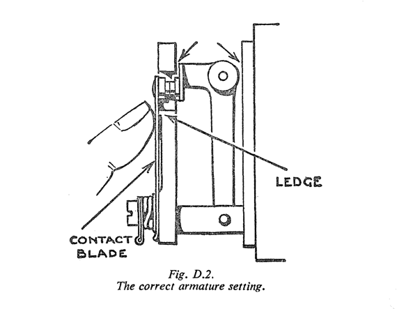
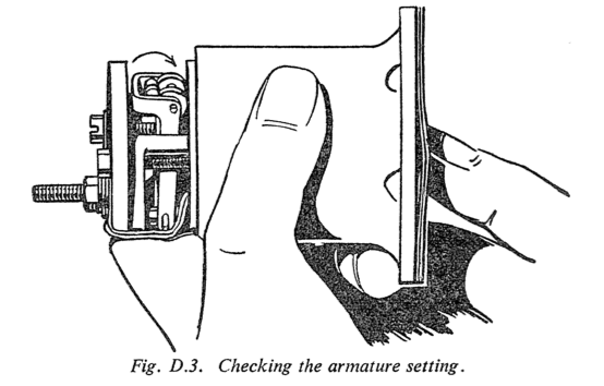
- If the contact blade has been removed, replace it underneath the tag, bearing directly against the pedestal. When the points are separated, the blade should rest against the ledge of the pedestal and must not be so stiff as to prevent "he outer rocker from coming right forward when the points are in contact. The points must make contact when the rocker is in the midway position. To check, hold the blade in contact with the pedestal without pressing on the overhanging portion, and test the gap between the white rollers and the body of the pump with a 0030in. (976 mm.). If necessary, set the tip of the blade to give the correct clearance.
Note.-Fit the spring washer on the earth connection screw between the tag and the pedestal as the spring washer is not a reliable conductor and the tag must bear directly against the head of the screw.
Solder the coil ends to their tags and the two termi- nals to the earthing wire.
The assembly of components on the terminal screw holding the cover in position is as follows: spring washer, wiring tag, lead washer and recessed nut. In no circumstances omit the spring washer or shorten the assembly in any way or the pedestal may be broken when the cover retaining nut is tightened.
Fit the armature return spring with its larger diameter towards the coil and the smaller to the armature. Do not stretch the spring.
Section D.4
FUEL PUMP ADJUSTMENT
If the armature has been removed, reassemble and adjust as follows :-
- Swing the contact blade on the pedestal to one - side.
- Fit the impact washer to the armature recess.
- Screw the armature into position.
- Place the eleven guide rollers in position around the armature. Use no jointing compound on the diaphragm.
- Hold the magnet assembly in an approximately horizontal position and push in the armature firmly and steadily. If the contact breaker throws over, screw the armature farther in until it ceases to do so; unscrew the armature one- sixth of a turn at a time until a position is found where the rocker just throws over. It is important to press steadily and not to jerk the armature. When the correct position is found unscrew the armature a further two-thirds of a turn; this is important.
When a new diaphragm is fitted it is probable that considerable pressure will be needed to push the armature right home. If there is any doubt concerning the point at which the contact breaker
throws over, turn it back one-sixth of a turn.
Place the magnet housing in position on the main body with the drain hole at the bottom; make sure that the rollers are still in their correct positions. If a roller drops it may get trapped between the two ports and cut a hole in the diaphragm.
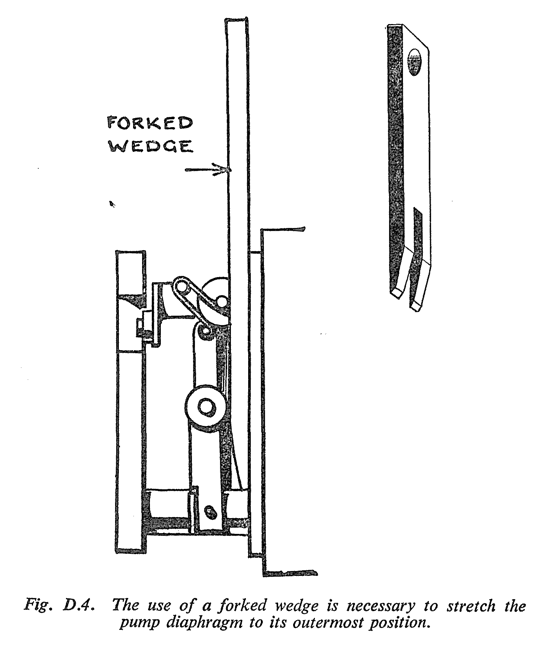
Insert the coupling screws and the earth terminal screw. Do not screw up tightly before stretching the diaphragm to its outermost position. This is best accomplished by the use of a wedge as shown in Fig. D.4. Insert the wedge between the white rollers of the outer rocker and pressed under the tips of the inner rocker until it lifts the trunnion in the centre of the inner rocker as far as it will go.
If no wedge is available, insert a matchstick under one of the white rollers and pass a current through the pump. This will excite the magnet, actuate the armature and stretch the diaphragm: the screws may then be tightened down fully while the diaphragm is held in this position. The spring blade rests against a small projection on the bakelite moulding, and it must be set so that when the points are in contact it is deflected back from the moulding. The width of the gap a t the points is approximately .030 in. (.76 mm.).Now place the pump on test, using a cut-away cover to allow observation of the contact breaker and prevent the hinge pin from falling out.
A test rig of the type illustrated in Fig. D.5 is advised and either petrol (gasoline) or parafin (kerosene) may be used for testing.
When the pump is switched on it should prime itself promptly and if there is any air leak in the pump or in its connections, bubbles will be seen coming out of the pipe projecting into the flow-meter. Bubbles normally appear when the pump is first started up but should cease to appear when the pump has been running for a minute or two.
Turn off the tap fully ; the pump should stand without repeating its action for at least 15 seconds, if not, the suction valve is not seating correctly.
Next, turn the tap off slowly and note whether the pump idles satisfactorily, and that the outer rocker comes fully forward and contacts the pedestal. While in this position, press the tip of the blade inwards to reduce the stroke of the pump gradually. However much the stroke is reduced the pump should continue to pump normally until it fails, when there is no gap left. If it buzzes instead of pumping, the cause is usually excessive flexibility in the diaphragm, and is unlikely to occur on a new one.
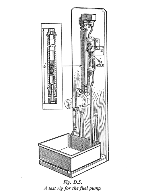
A test rig for the fuel pump.
Finally test the pump on 9 volts, when it should work satisfactorily though probably with a somewhat reduced output. Note.-Three important points, which will seriously affect the working of the pump if overlooked, are the following :-
- Keep the contact breaker blade out of contact while setting the diaphragm.
- Press firmly without jerking on the diaphragm.
- Stretch the diaphragm to its limit while tightening up the body screws.
Section D.5
TRACING PUMP TROUBLES
Should the pump cease to function, first disconnect the fuel delivery pipe from the pump. If the pump then works the most likely cause of the trouble is sticking needles in the float-chambers of the carburetters. Should the pump not work, disconnect the lead from the terminal and strike it against the body of the pump after switching on the ignition. If a spark occurs it indicates that the necessary current is available at the terminals, and that the trouble arises with the pump mechanism. If no spark can be detected, then it is an indication that the current supply has failed and that attention should be
given to the wiring and battery. If current is present further investigation should be carried out by removing the bakelite cover which is retained by the terminal nut. Touch the terminal with the lead. If the pump does not operate and the contact points are in contact yet no spark can be struck off the terminal, it is very probable that the contact points are dirty and require cleaning. These may be cleaned by inserting a piece of card between them, pinching them together and sliding the card back- wards and forwards.
If, when the wire is connected to the terminal and the tickler of the carburetter is depressed, the points fail to break, it is possible that there is either an obstruction in the suction pipe, which should be cleared by blowing it through with air, or some irregularity in the pump itself is preventing the correct movement. This may be due either to the diaphragm having stiffened, or to foreign matter in the roller assembly which supports the diaphragm, in which case the diaphragm should be removed and the whole assembly cleaned and reassembled in accordance with the instructions on page D.3.
On the other hand, if the points are not making contact, see that the tips of the inner rocker (25) (Fig. B.1) are in contact with the magnet housing. If they are not, it is an indication that the armature has failed to return to the end of its normal travel.
To cure this, loosen the six screws which attach the magnet housing to the pump body, and make sure that the diaphragm is not sticking to the face of the magnet housing by carefully passing a penknife between the two. The hinge pin (19) should then be removed and the six retaining screws tightened up again. The tips of the inner rockers will probably now be found to be making contact with the face of the magnet housing, but if they are not, it will be necessary to remove and dismantle the whole magnet assembly in order to ascertain if an accumulation of foreign matter has caused a jam. Remember that whenever the magnet housing is removed, care should be taken to see that the guide rollers (10) do not drop out.
Pump Noisy
If the pump becomes noisy and works rapidly, it is usually an indication that there is an air leak on the suction side of the pump. Check the level of the fuel in the tank and see that it is not too low.
The simplest way to test for air leakage is to dis- connect the fuel pipe from the carburetter and place its end in a glass jar (approximately 1 pint or half a litre) and allow the pump to deliver fuel into it. If air bubbles appear when the end of the pipe has become submerged in the fuel, it is a clear indication of an air leak on the suction side of the pump in the fuel feed pipe between the tank and the pump, which should be found and
cured. Check all the unions and joints, making sure that the filter union and inlet unions are all quite air- tight.
Failure to Deliver Fuel
Should the pump continue beating without delivering fuel, it is probable that some dirt has become lodged under one of the valves, in which case they should be dismantled by unscrewing the top or delivery union and lifting out the valve cage, when they can be cleaned and reassembled. When replacing it, see that the thin hard red fibre washer is below the valve cage and the thick orange one above.
If the pump struggles to pump and becomes very hot, it is probable that the filter has become clogged or there is an obstruction on the suction side. The filter is readily removed for cleaning by unscrewing its retaining plug at the bottom of the pump.
Section D.6
FUEL PUMP MAINTENANCE
Apart from keeping the contacts clean there is no maintenance required on the fuel pump.
The filter can be removed for cleaning by unscrewing the hexagon plug at the bottom of the pump. Clean the filter in fuel with a stiff brush: do not use a rag.
Many of the troubles encountered with the pump are a result of the terminals not being tight, resulting in poor connections. Make sure that the earth wire terminal, in particular, is quite tight.
Section D.7
THE CARBURETTERS
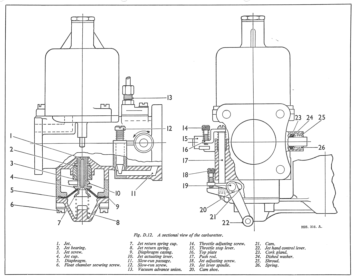
The two S.U,carburetters are of the variable jet type, fitted with air cleaners.
A damper is provided in each carburetter, consisting of a plunger and non-return valve attached to the oil cap nut, and operates in the hollow piston rod which is partly filled with oil. Its function is to give a slightly enriched mixture on acceleration by controlling the rise of the piston and to prevent piston flutter.
Section D.8
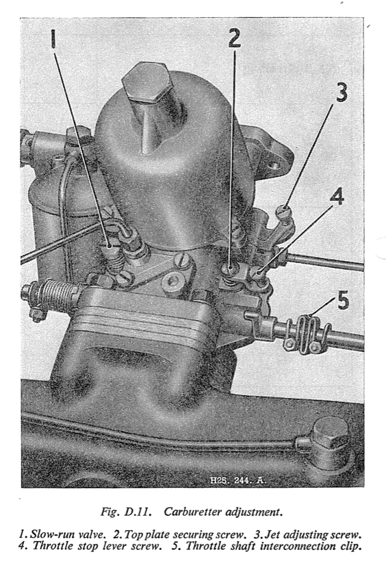
CARBURETTER ADJUSTMENT
It is first essential to run the engine until it has attained its normal running temperature before commencing any mixture or slow-running adjustments.
The slow-running is governed by the setting of the jet adjusting screws and the throttle stop screws, all of which must be correctly set and synchronised if satisfactory results are to be obtained.
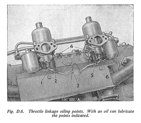
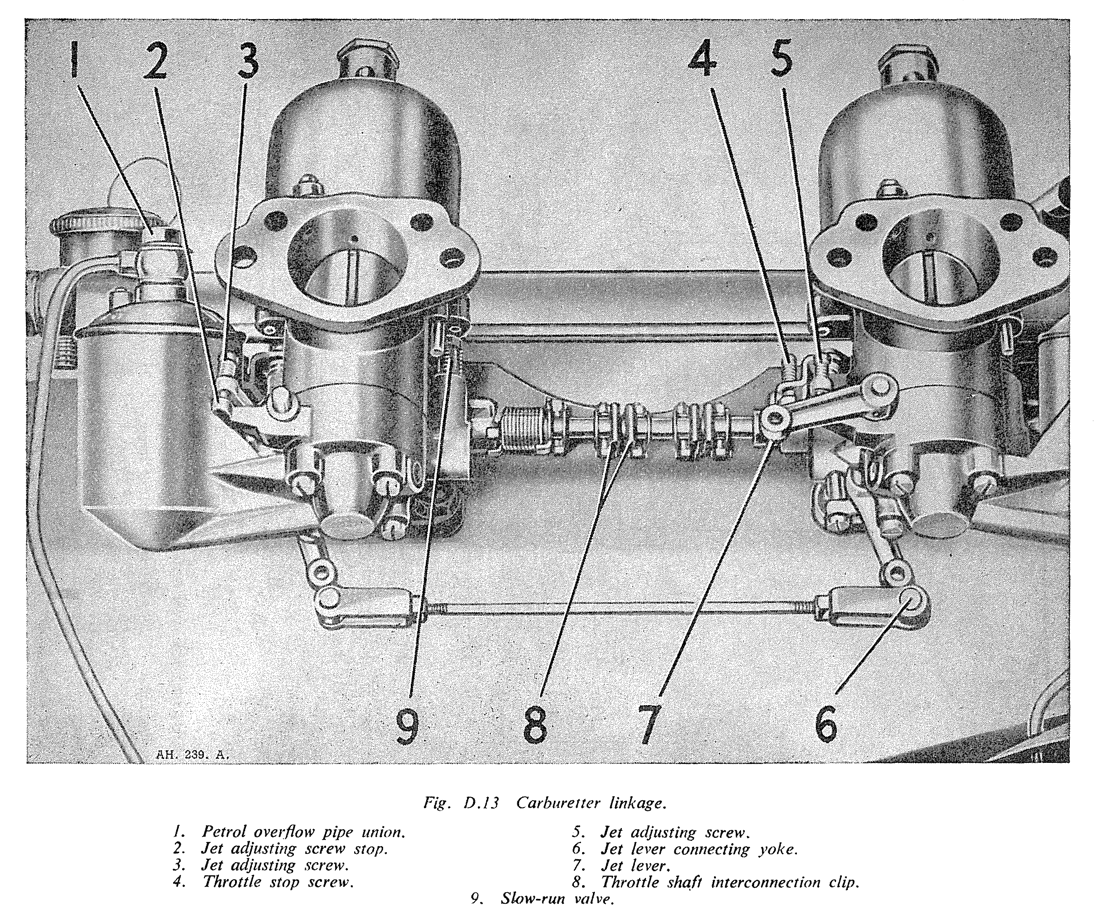
The two carburetter throttles are interconnected by a coupling shaft and spring coupling clips which enable them to be correctly synchronised when adjustments take place.
Before blaming the carburetter settings for bad slow-running, make quite sure that it is not due to badly set contact points, faulty plugs, bad valve clearance setting or faulty valves and valve springs.
Good slow-running cannot be obtained if the setting for the jets is incorrect. It is therefore advisable to commence any adjustments at this point.
In order to adjust the carburetters successfully it is necessary to remove the air cleaners and intake pipe assembly from the carburetters and engine valve cover and make sure the pistons work freely and the jets are properly centred (see below).
Adjusting the Jets
- Slacken off the pinch-bolt of one of the spring coupling clips locating the carburetter inter- connecting shaft to the carburetter throttle spindles and also release the two screws securing the choke spring to the jet levers, so that each carburetter can be operated independently.
- Release the throttle lever adjusting screws until both throttles are completely closed.
- Turn the throttle lever adjusting screw for the rear carburetter clockwise until it is just touching the web on the carburetter body and then give it one full turn. This will set the rear carburetter for fast idling and leave the front one out of action. This can be ensured further by lifting the front carburetter piston a matter of 1/2 in. (13 mm.)
- With the engine running, set the jet adjusting screw for the rear carburetter so that a mixture strength is obtained which will give the best running speed for this throttle opening, taking care to see that the jet head is kept in firm contact with the adjusting nut tlie whole time.
- The correctness or otherwise of this setting can be checked by raising the suction piston with a small screwdriver, or similar instrument, to the extent of 1/32 in. (1 mm,). This should cause a very slight momentary increase in the engine speed without impairing the evenness s f the running in any way.
If this operation has the effect of stopping the engine it is an indication that the mixture setting is too weak.
If an appreciable speed increase occurs and continues to occur when the piston is raised as much as 1/4 in. (6 mm.) it is an indication that the mixture is too rich. - When the rear carburetter mixture setting has been carried out correctly release its throttle adjusting screw so that it is clear of the stop and the throttle completely closed, and lift the piston 1/2 in. (13 mm.) to render it inoperative. Then repeat the jet-adjusting operations on the front carburetter.
- When both carburetters are correctly adjusted individually for mixture strength the throttles of each should be set so as to give the required slow-running and synchronisation.
Slow-running and Synchronisation
Screw each throttle lever adjusting screw so that
its end is only just making contact with the web on the carburetter body, then give each screw one full .turn exactly.
Start the engine, which will now idle on the fast side.
Unscrew each throttle lever adjusting screw an equal amount, a fraction of a turn at a time, until the desired slow-running speed is achieved.
Correct synchronisation can be checked by listening at each carburetter air intake in turn through a length of rubber tube and noticing if the noise produced by the incoming air is the same at both. Any variation in the intensity of the sound indicates that one throttle is set more widely open than the other-the louder sound indicating the throttle with the greater opening.
When the same intensity of sound is given by both carburetters the intercoupling shaft clip should be tightened up firmly to ensure that the throttles work in unison.
Since the delivery characteristics, when both carburetters are operating together, vary somewhat from those existing when each is working separately, it will be found necessary to check them again for correctness of mixture strength by lifting the pistons in turn as described in Adjusting the Jets,
making such adjustments of the jet adjusting screws as are required to balance the mixture strength and to ensure that it is not too rich.
Fitting New Needles
If the road performance is not satisfactory after the above adjustments have been made, larger or smaller needles may be necessary.
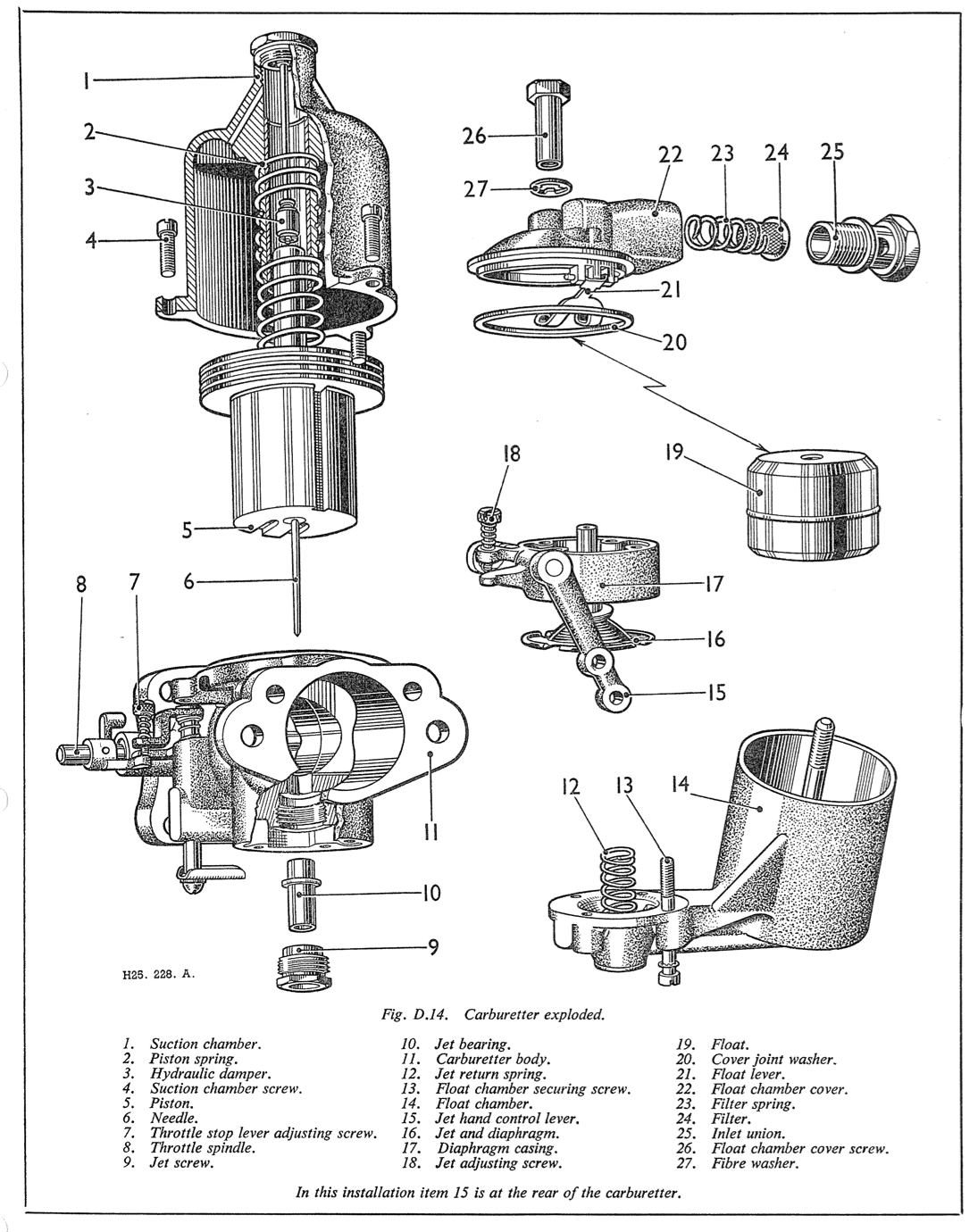
To change the needles, remove the screws and lift off the suction chambers, having marked them to ensure
their refitting to their respective carburetters, Remove the pistons and return springs.
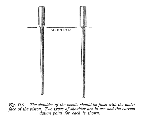
Unscrew the screw at the side of each piston tube and withdraw the needles.
Fit the new needles: a needle should be fitted with its shoulder flush with the face of the piston as shown in Fig. D.9.
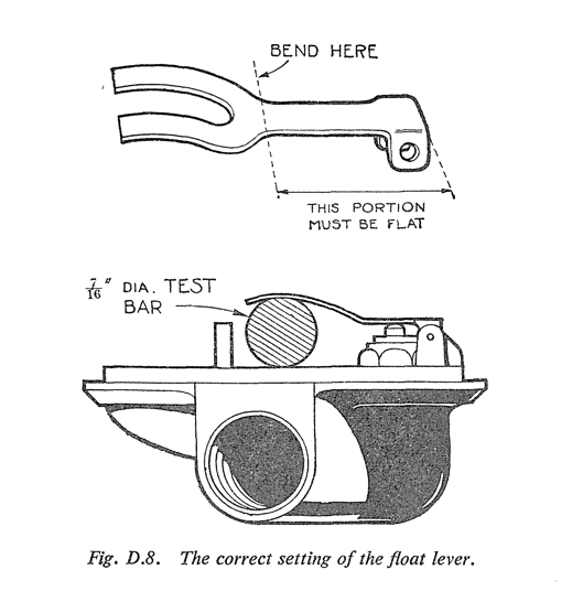
The Float-chamber
The position of the forked lever in the float-chamber must be such that the level of the float (and therefore the height of the fuel at the jet) is correct.
This is checked by inserting a 7/16 in. (11.11 mm.) round bar between the forked lever and the machined lip of the float-chamber lid. The prongs of the lever should just rest on the bar (see Fig. D.8) when the needle is on its seating. If this is not so, the lever should be reset at the point where the prongs meet the shank. Care must be taken not to bend the shank, which must be perfectly flat and at right angles to the needle when it is on its seating.
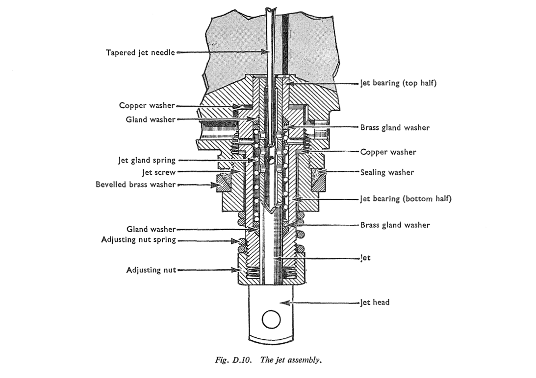
Centring a Jet
First remove the clevis pin at the base of the jet which attaches the jet head to the jet operating lever; withdraw the jet completely, and remove the adjusting nut and the adjusting nut spring. Replace the adjusting nut without its spring and screw it up to the highest position. Slide the jet into position until the jet head is against the base of the adjusting nut. When this has been done, feel if the piston is perfectly free by lifting it up with the finger with the dashpot piston removed. If it is not, slacken the jet holding screw and manipulate the lower part of the assembly, including the projecting part of the bottom half jet bearing, adjusting nut and jet head. Make sure that this assembly is now slightly loose. The piston should then rise and fall quite freely as the needle is now able to move the jet into the required central position. The jet holding screw should now be tightened and a check made to determine that the piston is still quite free. If it is not found to be so, the jet holding screw should be slackened again and the operation repeated. When complete freedom of the
piston is achieved the jet adjusting nut should be removed, together with the jet, and the spring replaced. The adjusting nut should now be screwed back to its original position.
Experience shows that a large percentage of carburetters returned for correction have had jets removed and incorrectly centred on replacement.
Section D.9
SOURCES OF CARBURETTER TROUBLE
Piston Sticking
The piston assembly comprises the suction disc and the piston forming the choke, into which is inserted the hardened and ground piston rod which engages in a bearing in the centre of the suction chamber and in which is, in turn, inserted the jet needle. The piston rod running in the bearing is the only part which is in actual contact with any other part, the suction disc, piston, and needle all having suitable clearances to prevent sticking. If sticking does occur the whole assembly should be cleaned carefully and the piston rod lubricated with a spot of thin oil. No oil must be applied to any other part except the piston rod. A sticking piston can be ascertained by removing the dashpot piston damper, inserting a finger in the air intake and lifting the piston, which should come up quite freely and fall back smartly onto its seating when released.
Water or dirt in the Carburetter
When this is suspected, lift the piston: the jet can then be seen. Flood the carburetter and watch the jet; if the fuel does not flow through freely there is a blockage. To remedy this, start the engine, open the throttle, and block up the air inlet momentarily without shutting the throttle, keeping the throttle open until the engine starts to race. This trouble seldom arises with the S.U. carburetter owing to the size of the jet and fuel ways
When it does happen the above method will nearly always clear it. Should it not do so, the only alternative is to remove the jet.
Float-chamber Flooding
This can be seen by the fuel flowing over the float- chamber and dripping from the air inlet, and is generally caused by grit between the float-chamber needle and its guide. The float-chamber lid should be removed and the needle and its guide thoroughly cleaned.
Float Needle Sticking
If the engine stops, apparently through lack of fuel, when there is plenty in the tank and the pump is working properly, the probable cause is a sticking float needle. An easy test for this is to disconnect the pipe from the electric pump to the carburetter, switch on the ignition to check if fuel is delivered; if it is, starvation has almost certainly been caused by the float needle sticking to its seating, and the float-chamber lid should therefore be removed, the needle and seating cleaned, and refitted. At the same time it will be advisable to clean out the entire fuel feed system, as this trouble is caused by foreign matter in the fuel, and unless this is removed it is likely to recur. It is of no use whatever renewing any of the component parts of the carburetter, and the only cure is to make sure that the fuel tank and pipe lines are entirely free from any kind of foreign matter or sticky substance capable of causing this trouble.
Section D.10
THE AIR CLEANERS
Remove the units and wash the gauze in fuel every 3,000 miles (4800 km.).
When the gauze is clean and dry, re-oil it with engine oil and allow it to drain before refitting to the engine