Section B.1
DESCRIPTION
The ignition system consists of two circuits-primary and secondary. The primary circuit includes the battery, ignition switch, the primary or low-tension circuit of the coil and the distributor contact breaker and capacitor. The secondary circuit includes the secondary of high-tension circuit of the coil, the distributor rotor and cover segments, the high-tension cables and the sparking plugs.
The ignition coil, which is mounted on the right-hand side of the engine, consists of a soft iron core around which is wound the primary and secondary windings. The coil carries at one end a centre high-tension terminal and two 10W tension terminals marked (SW) (switch) and (CB) (contact breaker) respectively.
The ends of the primary winding are connected to the (SW) and (CB) terminals and the secondary Winding to the (CB) terminal and the high-tension terminal.
The distributor is mounted on the right-hand side of the engine and is driven by a shaft and helical gear from the camshaft. Automatic timing control of the distributor is controlled by a centrifugal mechanism and a vacuum operated unit each operating entirely independently of each other. The centrifugal mechanism regulates the ignition advance according to engine speed, while the vacuum control varies the timing according to engine load. The combined effect of the two mechanisms gives added efficiency over the full operating range of the engine. A micrometer adjuster is provided to give a timing adjustment to allow for the engine condition and the grade of used.
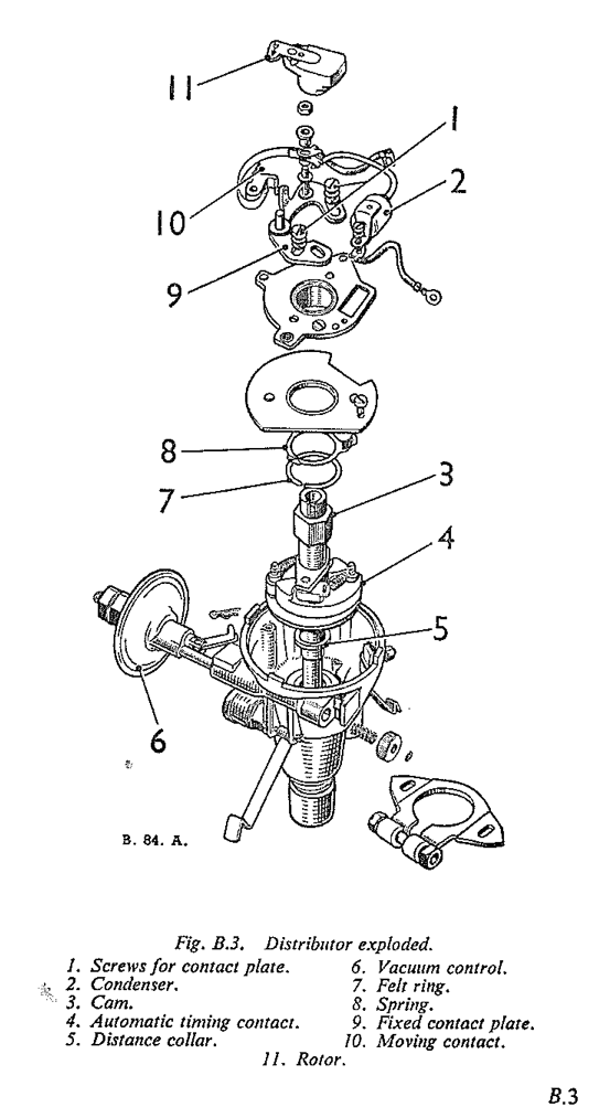
A keyed moulded rotor with a metal electrode is mounted on top of the cam. Attached to the distributor body above the centrifugal advance mechanism is a contact breaker plate carrying the contact breaker points and a capacitor connected in parallel. A cover is fitted over the distributor body and retained by two spring clips attached to the body.
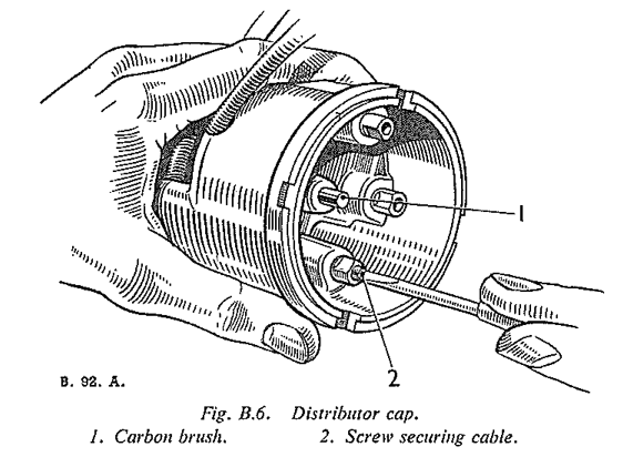
Inside the cover is a centre electrode and spring- loaded carbon brush which makes contact with the rotor. The brush is of composite construction, the top portion being made of a. resistive compound, the lower portion is made of softer carbon to prevent wear of the rotor electrode. Under no circumstances must a short non-resistive brush be used to replace this long resistive type. A measure of radio interference suppression is given by this brush.
Spaced circumferentially around the centre electrode are the sparking plug cable segments. The distributor is secured in position on the cylinder block by a clamp plate.
The sparking plugs are located on the right-hand side of the engine and have a 14 mm. thread with a 3/4 in. reach.
When the ignition is switched on, the current from the battery :Hows through the primary circuit, and a magnetic field is built up around the core of the coil. When the contact breaker points are opened by rotation of the distributor cam, the current flow is interrupted, causing a high voltage to be induced in the secondary winding of the coil by sudden collapse and consequent change in the magnetic field. The hightension current thus generated in the secondary winding of the coil is conveyed by the coil high-tension cable to the centre terminal of the distributor cover. From here the current passes through the carbon brush to the rotor, where the high-tension current passes along the rotor electrode and is distributed to the segments and thence to the sparking plugs Via the high-tension cables.
Section B.2
ADJUSTMENTS LN THE VEHICLE
The purpose of the following adjustments is to maintain efficient engine performance and economical running.
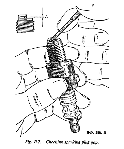
- Adjust the sparking plugs at the recommended intervals as follows - The gap of the plug points should be within the limits of .024 to .026 in. (.61 to .66 mm.).
Gap adjustment should be made by bending the side electrode only. Never bend the central electrode. If the plugs are dirty, damaged or excessively burned, see Section B.1.
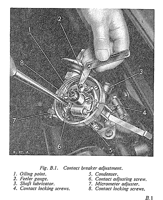
Adjust the contact breaker points at the recommended intervals as follows:- Remove the distributor cover and rotor. Rotate the engine with the starting handle until the fibre heel of the rocker is on the peak of one of the cam lobes. The gap of the contact breaker points should be within .014 to .016 in. (.36 to .40 mm.). Gap adjustment should be made by slackening the fixed contact plate securing screws and moving the plate the gap gauge is a sliding between the two contacts. Tighten the securing screws and recheck the gap. Replace the rotor and cover. if the points are dirty or pitted see Section B.5.
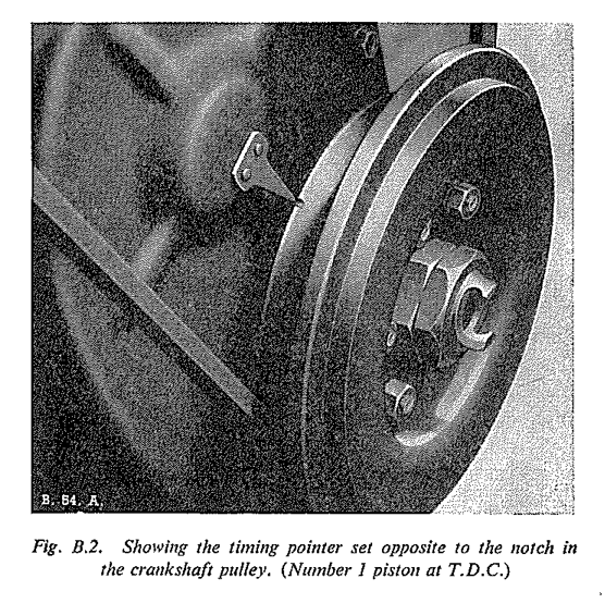
Adjust the ignition timing, if the distributor has been disturbed, as follows: - Remove the valve rocker cover so that the valve action can be observed. Rotate the engine with the starting handle until No. 1 piston is at the top of its compression stroke (i.e. the exhaust valve of No. 6 cylinder is just closing and the inlet valve just opening). Turn the crankshaft until the recess in the crankshaft pulley flange is in line with the pointer on the timing chain cover (See Fig. B.2). If the timing chain cover has been removed, align the bright links on the timing chain with the marked teeth on the camshaft and crankshaft sprockets (see Section A.25) when No. 6 and No. 1 pistons will be at T.D.C. Set the micrometer adjustment on the distributor to its central position. The crankshaft should now be rotated backwards to obtain its correct position before setting the distributor points, this setting is correct for premium grade fuels only. With the cover removed the distributor body must be rotated until the rotor arm is pointing to the position of No. 1 electrode in the cover. With the contact points just opening, tighten the clamp plate bolt.
Finer adjustment can be obtained under road conditions, by means of the micrometer adjustment. Note this adjustment should not be used for initial setting of the ignition; it is only altered if the main setting requires adjustment to meet the characteristics of the grades of petrol being used. There is a considerable amount of latitude for adjustment, but only extremely small movement of the adjustment knob should be made at one time.
Replace the distributor cover and cylinder head cover.
Section B.3
TO TEST IN THE VEHICLE
If the ignition System fails, or misfiring occurs, first make sure that the trouble is not due to defects in the engine, carburetter 01’ fuel supply. Faults should be diagnosed by applying the following tests -
Examine the cables, the cables from the coil to the distributor, and from the distributor to the plugs. If the rubber insulation shows signs of deterioration or cracking, the cable should be renewed.
Test the plugs and high-tension cables by removing the plugs in turn and allowing them to rest on the cylinder head or other convenient earthing point, and observing whether a spark occurs at the points when the engine is turned by hand. It should, however, be noted that this is only a rough test, since it is possible that a spark may not take place when the plug is under compression. If necessary, clean and test the plugs, using at plug cleaning and testing machine.
To trace a fault in the circuit, release the instrument panel from the dash, switch on the ignition, and turn the engine until the distributor contacts are opened. Refer to the wiring diagram, Fig. N.25, and, with the aid of a voltmeter (0 to 20), check the circuit as follows -
- Cable-Battery to starter switch
Connect the voltmeter between the supply terminal of the starter switch and an earthing point. No reading indicates a faulty cable or loose connection.
Cable (brown) - Starter switch to fuse unit A.1 terminal
Connect the voltmeter between the fuse unit A.1 terminal and earth. No reading indicates a faulty cable or loose connection.Control box
Connect the voltmeter between the control box terminal (A.1) and earth. No reading indicates a faulty control box.Cable (brown and blue) - Control box to lighting and ignition switch
Connect the voltmeter between the lighting switch terminal (A) and earth. No reading indicates a faulty cable or loose connection.Ignition switch
Connect the voltmeter between the ignition switch (white cable terminal) and earth. No reading indicates a faulty ignition switch.Cable (white) - Ignition switch to fuse unit A.3 terminal
Connect the voltmeter between the fuse unit A.3 terminal and earth. No reading indicates a faulty cable or loose connection.Cable (white) - Fuse unit A.3 terminal to ignition coil
Connect the voltmeter between the ignition coil terminal (SW) and earth. No reading indicates a faulty cable or loose connection.Ignition coil
Connect the voltmeter between the ignition coil terminal (CB) and earth. No reading indicates a faulty ignition coil.Cable (white and black) - Ignition coil to distributor
Connect the voltmeter between the distributor terminal and earth. No reading indicates a faulty cable or loose connection.Distributor
Connect the voltmeter across the distributor contacts. If no reading is given, remove the capacitor and test again. if a reading is given, the capacitor is faulty.
- If, after carrying out the foregoing tests, the fault has not been located, remove the high-tension cable from the centre terminal of the distributor. Switch on the ignition and crank the engine until the contacts close. Flick the contact breaker lever open while the high-tension cable from the ignition coil is held about 3/16 in. (5 mm.) away from the cylinder block. If the ignition equipment is in spark should be obtained. If no spark is given, it indicates a faulty ignition coil.
Section B.4
IGNITION COIL
To remove
- Disconnect the high-tension cable from the coil centre terminal.
- Disconnect the low-tension cables from the (SW) and (CB) terminals of the coil.
- Unscrew the bolts fastening the coil to the generator strap, and remove the coil.
To install
The installation of the ignition coil is a reversal of the procedure To remove
.
Section B.5
DISTRIBUTOR
To remove
- Disconnect the high tension cables from the sparking plugs.
- Disconnect the high-tension cable from the centre terminal of the ignition coil.
- Disconnect the low-tension cable terminal on the side of the distributor.
- Disconnect the vacuum control pipe at the union.
- Unscrew and remove the tachometer drive and tachometer drive oil feed pipe.
- Remove the two set bolts attaching the clamp plate to the tachometer drive housing and with- draw the distributor from the tachometer housing. Do not loosen the clamp plate.
To dismantle
- Spring back the two securing clips and remove the distributor cover.
- Unscrew the terminal screws from the distributor cover and Withdraw the hightension cables.
- Remove the rotor.
- Take out the split pin securing the vacuum link to the sliding contact breaker plate and remove the two screws at the edge of the contact breaker base.
- Slacken the two nuts on the low tension terminal and pull the connection on the contact breaker away from the terminal block. Lift out the contact breaker assembly.
- Remove the nut, insulating piece and connections from the pillar on which the contact breaker spring is anchored, and lift off the contact breaker lever and the insulating washers beneath it.
- Remove the two screws securing the fixed contact plate, together with their spring and plain washers and take off the plate.
- Withdraw the single screw securing the capacitor and contact breaker earthing lead. The contact breaker base assembly can be dismantled by removing the cîrclip and star washer located under the lower plate.
- Remove the circlip on the end of the micrometer timing screw and turn the micrometer nut until the screw and vacuum assembly are freed, take care not to loosen the ratchet and coil springs located under the micrometer nut.
- Tap out the parallel pin securing the driving dog and tachometer gear to the lower end of the spindle. The driving dog and tachometer gear can then be removed.
- Unscrew and remove the lubricator from the distributor body together with its spring and felt washer.
- The distributor shaft, cam and centrifugal timing control can be pressed upwards through the distributor body.
- Remove the cam fixing screw from the top of the driving shaft and withdraw the cam and centrifugal timing control.
Note: A distance collar is fitted on the shaft underneath the action plate. - Clean the distributor cover and examine it for signs of cracks and evidence of
tracking
, a conducting path may have formed between adjacent segments. This is indicated by a thin ‘black line between the segments; when this has occurred the cover should be renewed. - Ensure that the carbon brush moves freely in the distributor cover.
- Examine the attachment of the metal electrode to the rotor moulding. If slack or abnormally burned, renew the rotor.
- The contact face of the contact breaker points should present a. clean, greyish, frosted appearance. If burned or blackened, renew the contact set or polish the contact face of each point with a working with a rotary motion. Care should be taken to maintain the faces of the points fiat and square, so that when reassembled full contact is obtained. Clean the points thoroughly in petrol.
- Cheek that the movable contact arm is free on its pivot without slackness.
Twenty-to-two position
- Check the centrifugal timing control balance weights and pivot pins for wear and renew the cam assembly or weights if necessary.
- The cam assembly should be a free sliding fit on the driving shaft. If the clearance is excessive or the cam face is worn renew the cam assembly or shaft as necessary.
To reassemble
Reassembly of the distributor is 5. reversal of the procedure To dismantle
, noting the following points:-
- Apply a few drops of engine oil to the centrifugal timing control mechanism and cam bearing.
- Lightly smear the cam surface with engine oil.
- Apply a drop of engine oil to the top of the pivot on which the moving contact fibre rocker arm works.
- Secure the distributor driving dog to the driving spindle with a new peg, ensuring that the small offset of the driving tongue is on the right when the rotor arm driving slot is downwards.
- Connect the internal cables as follows:-
- Red cable, capacitor to contact breaker spring anchor post.
- Cable, low tension terminal to contact spring anchor post.
- Cable, base plate locating screw to capacitor locating screw.
- Adjust the contact breaker points to the instructions given in Section B.2.
- Reassemble the high-tension cables to the distributor to the instructions given in Section B.7.
- Turn the vacuum control adjusting nut to the half-way position when refitting the unit.
To Install
Replacing the distributor to the reverse of the procedure To Remove
, noting the following points -
- Insert the assembled distributor, with its cap removed, into the tachometer housing and turn the rotor arm until the driving slot on the distributor engages with the dog in the housing.
- Turn the distributor body to align the clamping plate holes with their respective holes on the tachometer housing and not the set bolts.
- Check the contact breaker gap and ignition timing as described in Section B.2
- When replacing the distributor cap, renew the coating of Silicone grease on the lip of the cap and the ends of the leads where they enter the holes in the moulding.
Section B.6
DISTRIBUTOR DRIVING SPINDLE
Removal
- Remove the distributor as described in Section B.5
- Release the three setscrews which secure the tachometer housing to the cylinder block and withdraw the housing.
- By using a 5/16 in. U.N.F. bolt approximately 3 1/4 in. long, screwed into the tapped end of the drive spindle, the spindle can be withdrawn.
- Examine the drive gear for worn teeth.
To Replace
- Remove the valve rocker cover (see Section A).
- Crank the engine until No. 1 piston is at the top of its compression stroke (i.e. the exhaust valve of No. 6 cylinder is just closing and the inlet valve just opening).
- Turn the crankshaft until the recess in the crankshaft pulley flange is in line with the (T.D.C.) indicating pointer on the timing chain cover (see Fig. B.2.).
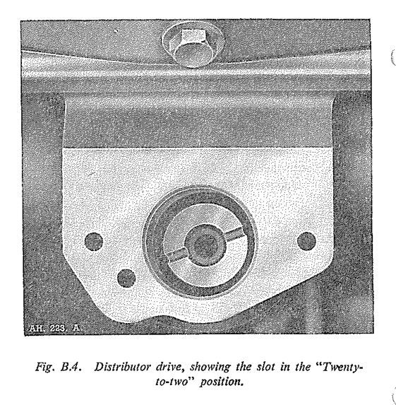
- Screw the 5/16 in. U.N.F. bolt into the threaded end of the distributor drive and replace the drive in the block so that the centrally out slot takes up the position shown in Fig. B.4 (i.e.
twenty-to-two
position).
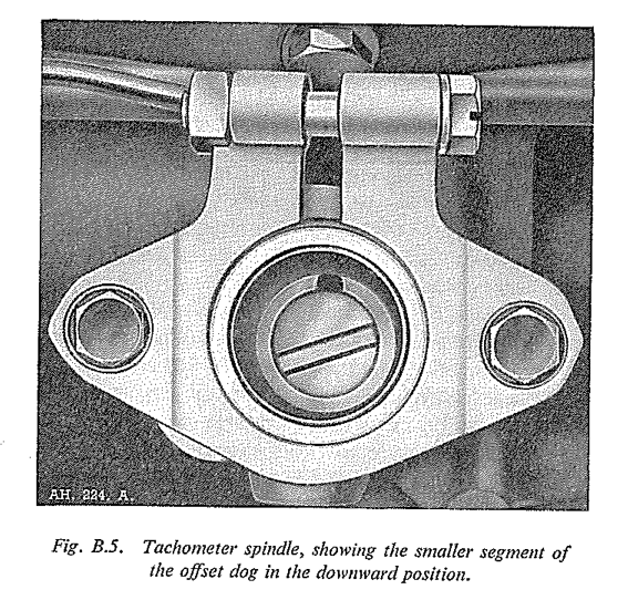
Replace the tachometer housing, rotating the external drive dog until it mates up with the slot in the distributor driving spindle. Ascertain that the smaller segment of the offset dog, situated within the tachometer housing is in the downward position.
Note: The internal dog should now be in thetwenty-to-two
position, see Fig. B.5. Secure the tachometer housing to the block with its three setpins.Replace the distributor following the instructions given in Section B.5.
Section B.7
HIGH-TENSION CABLES
To remove
- Pull the high-tension cable off the sparking plug.
- Unscrew the moulded terminal to release the cable from the coil.
- Straighten out the bare strands of cable, remove the brass washer and withdraw the cable from the moulded terminal.
- Release the screw securing the in the distributor cover and withdraw the cable.
To Replace
- Thread the cable through the moulded terminal and brass washer and bend back the bare strands of the cable against the brass washer.
- To fit the cables to the distributor cap, the cable sockets in the cap with Silicone grease, push the cables completely home, and then secure with the pointed screws. a smear of Silicone grease to the lip of the cap.
- Install the cables in the coil and distributor over and onto the sparking plugs in the correct order. The firing order is 1, 5, 3, 6, 2, 4, following round in an anti-clockwise direction.
Section B.8
SPARKING PLUGS
The sparking plug gap (for type of plug see General Data
) should be maintained at .024 to .026 in. (.6096 to .660 mm). If the gap is allowed to become too wide, misfiring at high speeds is liable to occur; and if too small, bad slow running and idling will be the result.
Sparking plugs should be regularly inspected, cleaned and tested. This is of vital importance to ensure good engine performance, coupled with fuel economy.
When removing the plugs from the engine, use a box spanner, this will avoid possible damage to the insulators. Always remove the copper washers. The plugs should then be placed in a suitable holder which has holes drilled to admit the upper end of the plugs and marked to identify each one with the cylinder from which it was removed.
The plugs should now be carefully examined.
Oil fouling will be indicated by a Wet shiny black deposit on the insulator. This condition is usually caused by worn cylinders, pistons or gummed rings. Oil vapour is forced from the crankcase, during the suction stroke of the piston which fouls the plugs.
Petrol fouling will cause a dry, fluffy, black deposit to be apparent on the plugs. This is usually caused by faulty carburation, but a faulty coil or leaking and worn out ignition leads, may have the same
Under the above conditions, if the plugs otherwise appear to be sound, they should be cleaned thoroughly, adjusted, and tested.
When preparing for cleaning, the plug washers should be removed and examined. The condition of these washers is important in that a large proportion of the heat from the plug insulator is dissipated to the cylinder head by them. The washer should therefore be reasonably compressed. A loose plug can be easily overheated, thus shortening plug life. On the other hand, do not over-tighten. All that is needed is a good seal between the cylinder head and the plug. Tightening too much will cause distortion of the washer with the possibility of blow-by which will again lead to over- heating and resulting danger. If there is any question of defect, replace with new washers.
The plugs should now be thoroughly cleaned of all carbon deposit, resorting to scraping if necessary, removing as much as possible from the space between the insulator and shell. An oily plug should be washed out with petrol. If a plug cleaning machine is available, 5 to 10 seconds in this will remove all remaining signs of carbon. Remember to thoroughly blow-out the
plug after treatment under these conditions, in order to remove all traces of abrasive.
After cleaning, thoroughly examine the plug for cracked insulator or worn away insulator nose. Should either of these conditions be apparent a new plug should be installed.
Carbon deposit on the threads of the plugs, should be carefully removed by using a wire brush, or if available a wire buffing wheel. Take care not to damage the electrodes or insulator tip. Neglect of this cleaning operation will lead to tight threads and resultant loss of heat dissipation due to the carbon deposit, thereby causing overheating.
The condition of the electrodes should now be noted and any signs of corrosion removed, if it is felt that the plugs are worthy of further use. This can be carried out with the use of a small file to carefully dress the gap area. The gap should then be reset, to a Clearance of .024 to .026 in. (.6096 to .660 mm.). When resetting bend the side electrode only.
It is advisable whilst the plugs are under pressure in the testing machine, to apply a spot of oil to the terminal end, to check for air leakage. Excessive leakage here will tend to cause compression loss, rapid deterioration of the electrode and overheating of the electrode tip. The top half of the insulator should be carefully examined for any paint splashes or accumulation of grime and dust, which should be removed. Should there be any signs of cracks due to faulty use of the spanner, the plug should be renewed. When replacing the plug lead, make sure that it is securely attached.
It is recommended that sparking plugs should be cleaned and tested every 6,000 miles (9600 km.), and renewed at 12,000 miles (19200 km.).
Remember, plugs in good condition will ensure better fuel consumption and good engine performance.
Section B.9
N.5 SPARKING PLUGS
Commencing at engine No. 6375, Champion N.5 plugs were fitted instead of Champion N.3 plugs. The N.3 plugs must however, be used for competition and high speed work.