Section E.1
DESCRIPTION
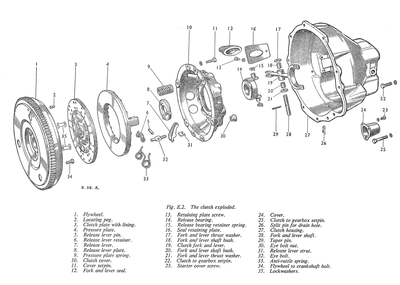
The clutch is a Borg & Beck single dry-plate-type operated hydraulically. A steel cover bolted to the flywheel encloses the driven plate, the pressure plate, the pressure springs, and the release levers. The driven plate, to which the friction linings are riveted, incorporates springs assembled around the hub to absorb power shocks and torsional vibration. The pressure springs force the pressure plate against the friction linings, gripping the driven plate between the pressure plate and the engine flywheel. When the clutch pedal is depressed, the release bearing is moved forward against the release plate which bears against the three levers. Each release lever is pivoted on a floating pin, which remains stationary in the lever and rolls across a short, flat portion of the enlarged hole in the eyebolt. The outer ends of the eyebolts extend through holes in the clutch cover and are fitted with adjusting nuts, by means of which each lever is located and locked in position. The outer or shorter ends of the release levers engage the pressure plate lugs by means of struts which provide knife-edge contact between the outer ends of the levers and the pressure plate lugs, so eliminating friction at this point. Pressure applied by the release bearing causes the pressure plate to be pulled away from the driven plate, compressing the pressure springs which are assembled between the pressure plate and the clutch cover. As the friction linings wear, the pressure plate moves closer to the flywheel face and the outer or shorter ends of the release levers follow. This causes the inner or longer ends of the levers to travel farther towards the gearbox and decreases the clearance between the release lever plate and the release bearing. This is automatically compensated unless the master cylinder has been disturbed.
When the clutch pedal is depressed, fluid pressure is transmitted through the master cylinder to the slave cylinder, which is mounted on the clutch housing, moving the slave cylinder piston, and push rod. As the push-rod is connected to the lower arm of the clutch withdrawal lever, thereby the clutch is released. The push rod is non-adjustable.
Section E.2
ADJUSTMENT IN VEHICLE
Owing to the hydraulic design of the clutch controls no adjustment is necessary to the clutch pedal.
Section E.3
CLUTCH ASSEMBLY
To Remove
- Remove the gearbox as described in Section F.
- Slacken the clutch cover screws a turn at a time by diagonal selection until the spring pressure is relieved, when the screws can be taken out and the clutch removed.
To Dismantle
When dismantling the clutch cover assembly the following parts should be suitably marked so that they can be reassembled in exactly the same relative positions to each other to preserve the balance and adjustment- the cover, the lugs on the pressure plate, and the release levers.
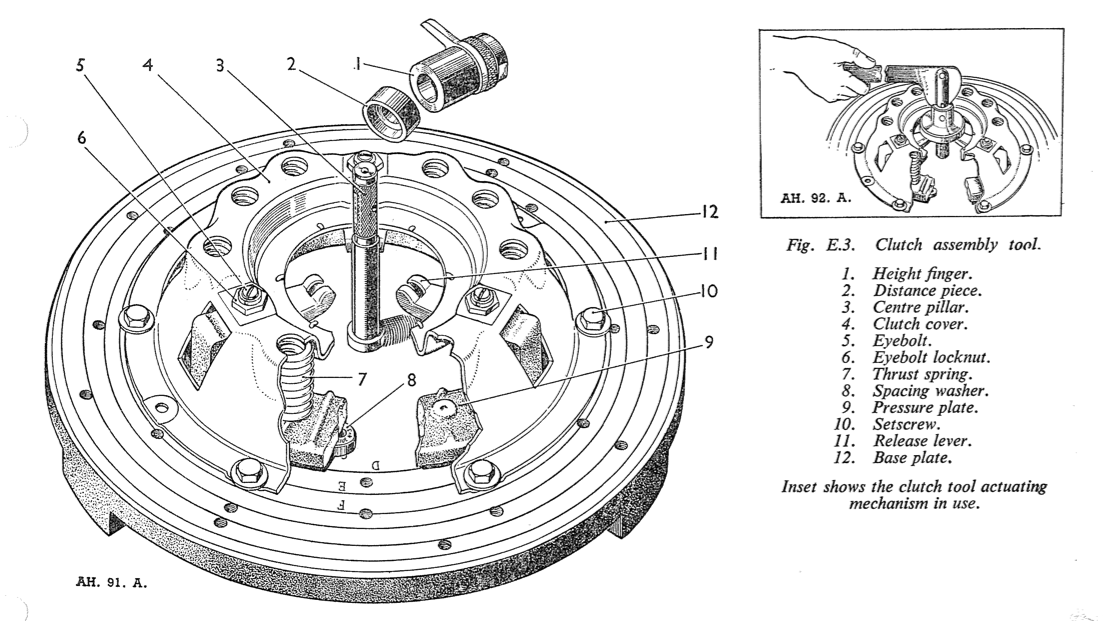
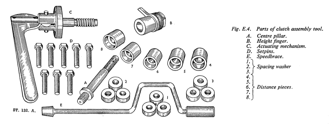
The clutch Tool No. 18G 99A provides an efficient and speedy means of dismantling, reassembling and adjusting the clutch with a high degree of accuracy. The tool is universal, and a chart detailing the sizes of spacing washers and distance-pieces for particular types of clutch is provided on the inside of the metal container lid. Proceed as follows :-
- Detach the retaining springs from the release lever plate and remove the springs and plate.
- Rest the tool base plate on a flat surface, ensure that it is clean, and place upon it spacing washers as directed by the chart. For this 9 in. (22.9 cm.) clutch select three washers and place them in position
D
on the base plate. - Position the clutch on the three spacing washers so that the hole in the clutch cover align with the tapped holes in the base plate, with the release levers as close to the spring washers as possible.
- Insert the tool setscrews, tightening them a little at a time in a diagonal pattern, until the cover is firmly and evenly secured to the base plate. This is most important if the best results are to be achieved.
- Remove the three eyebolt adjusting nuts, sheering away the peening by initial pressure.
- Unscrew the setscrews securing the clutch cover to the base plate in a diagonal pattern, releasing the pressure on the clutch springs gradually and evenly. Lift off the cover and remove the pressure springs.
- To remove the release levers, remove the anti- rattle springs, grasp the lever and eyebolt between the thumb and fingers, so that the inner end of the lever and the threaded end of the eyebolt are as near together as possible, keeping the eyebolt pin seated in its socket in the lever. The strut can then be lifted over the ridge onto the end of the lever, making it possible to lift the eyebolt off the pressure plate.
- Clean the clutch parts carefully. If the linings are to be used again they should not be allowed to come in contact with cleaning fluids.
- Examine the friction linings for wear or loose rivets and check the driven plate for uneven or worn splines, distortion or signs of fatigue cracks. Generally, it is not desirable to fit new friction linings on the original driven plate because refaced driven plates often are distorted or otherwise impaired and produce unsatisfactory clutch action. If renewing old worn linings, the rivets should be drilled out, not punched out.
- After refacing, mount the driven plate on a mandrel between centres and check for
run-out
by means of a dial gauge, set as near to the edge as possible. Where therun-out
exceeds .015in. ( .38 mm.), true the plate by prising it in the requisite direction after finding the high spots. - Examine the machined face of the pressure plate. If this is badly grooved and rough, the surface may be reground until the grooves disappear.
- Examine the machined surface of the release lever plate. If this is badly grooved, renew the plate. A new plate will also be necesssary if the surfaces on the reverse side of the plate, which are in contact with the tips of the release levers, are worn down.
- Examine the tips of the release levers which bear on the back of the release lever plate. A small amount of worn flat surface is permissible, but if this is excessive the lever should be renewed. Check for excessive wear in the groove in which the strut bears. Examine carefully the
U
- shaped depression in the lever into which fits the eyebolt floating pin. If the metal here has worn at all thin, the lever must be renewed as there is a danger of it breaking under load with disastrous results to the whole clutch mechanism.
- Examine each eyebolt for flats on the surface which fits into the pressure plate. If it is a loose fit, it must be renewed. The same applies to the eyebolt floating pin where it passes through the eyebolt. It should be a free fit, but not too loose.
- Examine the release bearing for cracks or bad pitting, also measure the amount of bearing standing proud of the metal cup. If the bearing is cracked or badly pitted, or there is & in. (1.6 mm.) or less of bearing standing proud of the cup, the cup and bearing must be renewed.
- Examine the pressure springs for weakness or distortion and renew if necessary. Renew in sets only.
- Examine the clutch withdrawal shaft for slackness in the bushes. Renew the bushes if necessary.
To Reassemble
Before reassembly note the positions of the marked parts and make sure to replace them in their original locations to preserve balance, unless the parts have been renewed. Using Tool No. 18G 99A, proceed as follows :-
- Position the pressure plate on the three spring washers on the base plate as described under
To Dismantle
. - Install the release lever, eyebolt and eyebolt pin, holding the threaded end of the eyebolt and the . inner end of the lever as close together as possible. With the other hand insert the strut in the slots in the pressure plate sufficiently to allow the plain end of the eyebolt to be inserted in the hole provided in the pressure plate. Move the strut upwards into the slots in the pressure plate lug, over the ridge on the short end of the lever, and drop it into the groove formed in the lever. Fit the remaining release levers in a similar manner. A very slight smear of grease should be applied to the release lever pins, contact faces of the struts, eyebolt seats in the clutch cover, drive lug sides on the pressure plate and the plain end of the eyebolts.
- Place the pressure springs on the bosses on the pressure plate.
- Lower the cover over the assembled parts, ensuring that the anti-rattle springs are in position and that the tops of the pressure springs are directly under their seats in the cover. In addition the machined portions of the pressure plate lugs must be directly under the slots in the cover through which they will pass.
- Insert the tool setscrews through the cover holes and screw them into the base plate in a diagonal pattern, a little at a time, to prevent distortion. Guide the eyebolts and pressure plate lugs through the holes in the clutch cover during this gradual tightening down.
- Screw the adjusting nuts onto the eye bolts. The clutch must now be adjusted still using the clutch assembly tool. With the clutch bolted to the tool base plate as on completion of assembly, proceed as follows:-
- Screw the actuator into the base plate and pump the handle a dozen times to settle the clutch mechanism. Remove the actuator.
- Screw the tool centre pillar into the base plate and select a distance-piece, Code No. 7, as shown on the chart. Place the distance-piece over the centre pillar with its recessed face downwards.
- Place the gauge height finger over the centre pillar.
- Adjust the height of the release levers by tightening or loosening the eyebolts until the height finger, when rotated, just contacts the highest point on the tips of the release levers. Press downwards on the height finger to ensure that it bears squarely on the adaptor while rotating.
- Remove the height finger and pillar, and screw in the actuator to the base plate. Operate the clutch several times to enable the components to settle on their knife edges. Remove the actuator and replace the centre pillar, distance-piece and height finger. Readjust the release levers if necessary. Repeat the procedure to ensure that the release levers are finally seated, and gauge once more.
- Remove the centre pillar, distance-piece and height finger and peen over the release lever adjusting nuts.
- Fit the release lever plate on the tips of the release levers and secure it by the three retaining springs.
- Release the tool setscrews in diagonal sequence a little at a time, relieving pressure slowly and evenly. Remove the clutch assembly from the base plate.
To Replace
Before installing the clutch assembly the engine flywheel should be checked for misalignment (see Section A). To install the clutch proceed as follows :-
- Hold the clutch cover assembly and driven plate on the flywheel and screw in the cover securing bolts finger-tight. Note that the splines in the hub of the driven plate are chamfered at one end to permit ready entry of the first motion shaft splines. The longer side of the driven plate hub, with the chamfered splines, should be toward the rear.
- Insert a pilot shaft or an aligning arbor No. 18G 79, through the clutch cover and driven plate hub so that the pilot enters the spigot bearing in the rear end of the engine crankshaft. This will centralise the driven plate.
- Tighten the clutch cover securing bolts a turn at a time in diagonal sequence to avoid distorting the cover.
- Remove the pilot shaft or aligning arbor. (5) Install the gearbox (see Section F.).
Section E.4
CLUTCH PEDAL
To Remove
- The clutch and brake pedal linkages are mounted in a common bracket and thus have to be released as a unit.
- Inside the car disconnect the clutch and brake cylinder levers from their master cylinder push rods by removing the clevis pins.
- Working under the bonnet unscrew the six securing setpins sufficiently to allow the clutch and brake pedal linkage bracket to be withdrawn from inside the car.
- Release the clutch and brake pedal return springs. (5) Unscrew the nut securing the clutch and brake pedal shaft and withdraw the shaft to release the clutch and brake pedal levers together with their distance piece.
- Inspect the lever bushes for wear and renew if necessary.
To Replace
Replacement is the reverse of the procedure To Remove
.
Section E.5
MASTER CYLINDER
Description
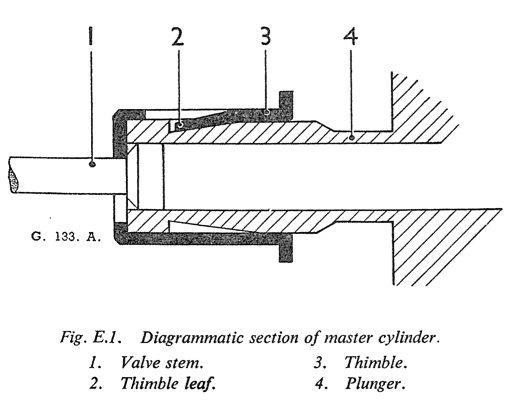
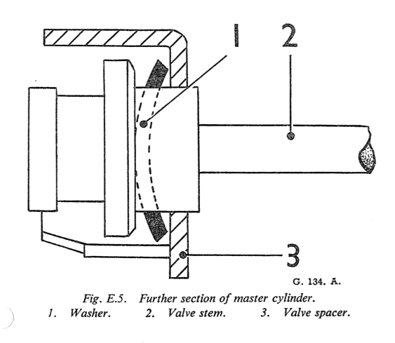
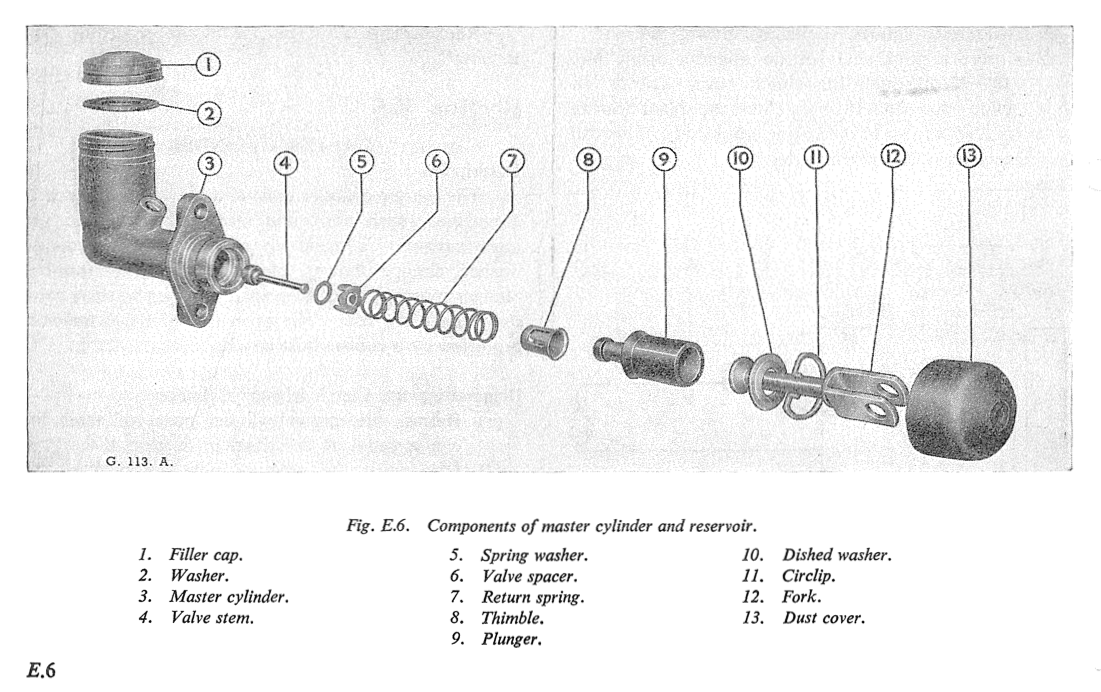
The master cylinder consists of an alloy body with a polished finish bore, and reservoir with cap. The inner assembly is made up of the push rod, dished washer, circlip, plunger, plunger seal, spring thimble, plunger return spring, valve spacer, spring washer, valve stem and valve seal. The open end of the cylinder is protected by a rubber dust cover.
Dismantling the Clutch Master Cylinder
- Release the master cylinder push rod from the clutch pedal as described in Section E.4.
- Disconnect the pressure pipe union from the cylinder and remove the securing bolts, then ?he master cylinder and fluid reservoir may be withdrawn complete from the car.
- Remove the filler cap and drain out the fluid. Pull back the rubber dust cover and remove the circlip with a pair of long nosed pliers. The push rod and dished washer can then be removed.
- When the push rod has been removed the plunger with seal attached will be exposed; remove the plunger assembly complete. The assembly can be separated by lifting the thimble leaf over the shouldered end of the plunger.
- Depress the plunger return spring allowing the valve stem to slide through the elongated hole of the thimble thus releasing the tension on the spring.
- Remove the thimble, spring and valve complete.
- Detach the valve spacer, taking care not to lose the spacer spring washer which is located under the valve head. Remove the seal.
- Examine all parts, especially the seals, for wear or distortion and replace with new parts where necessary.
Assembling the Clutch Master Cylinder
- Replace the valve seal so that the flat side is correctly seated on the valve head.
- The spring washer should then be located with the dome side against the underside of the valve head, and held in position by the valve spacer, the legs of which face towards the valve seal.
- Replace the plunger return spring centrally on the spacer, insert the thimble into the spring and depress until the valve stem engages through the elongated hole of the thimble, making sure the stem is correctly located in the centre of the thimble. Check that the spring is still central on the spacer.
- Refit a new plunger seal with the flat of the seal seated against the face of the plunger. Insert the seduced end of the plunger into the thimble until the thimble leaf engages under the shoulder of the plunger. Press home the thimble leaf.
- Smear the assembly with the recommended brake fluid, and insert the assembly into the bore of the cylinder valve, end first, easing the plunger seal lips in the bore.
- Replace the push rod with the dished side of the washer under the spherical head, into the cylinder followed by the circlip which engages into the groove machined in the cylinder body.
- Replace the rubber dust cover and refit the whole unit into its aperture in the scuttle, not forgetting to fit the packing washer first. Secure the unit by means of the two bolts on the flange and refit the pressure pipe union into the cylinder.
- Reconnect the push rod fork with its corres- ponding hole in the clutch pedal lever, securing it with the circlip.
- Bleed the hydraulic system.
Section E.6
SLAVE CYLINDER
Description
The cylinder is bolted to the clutch housing and comprises a piston, rubber cup, cup filler, spring, push- rod and bleeder screw. Fluid from the master cylinder is delivered through a flexible hose leading from a union in a bracket on the longitudinal member.
To Remove
- Place a receptacle to catch the fluid and remove the flexible hose from the slave cylinder. Note that the thicker washer on the hose connection is nearest the cylinder.
- Remove the split pin and clevis pin from the clutch withdrawal lever jaw end, thus freeing the slave cylinder push rod.
- Remove the two bolts and spring washers securing the cylinder to the clutch housing.
To Dismantle
- Remove all dirt from the outside of the cylinder.
- Remove the rubber dust cap from the bleed nipple9 attach a bleed tube, open the bleed screw three- quarters of a turn and pump the clutch pedal until all the fluid has been drained into a clean container.
- Unscrew the pressure pipe union at the cylinder and remove the setpins from the flange. The slave cylinder can now be removed.
- Remove the rubber cover and if an air line is available, blow out the piston and seal. The spring can also be removed.
- Clean the slave cylinder components, using only hydraulic fluid or alcohol, The main casting may be cleaned with any of the normal cleaning fluids, but all traces of the cleaning fluid must be dried out.
- Dry off and examine all rubber components and renew them if they are swollen, distorted or split. If there is any doubt at all as to their condition they must be renewed.
- Inspect the piston and cylinder bore for wear and scores, and renew them as necessary.
Assembling the Slave Cylinder
- Place the seal into the stem of the piston, with the back of the seal against the piston.
- Replace the springs with the small end on the stem, smear well with the recommended fluid and insert into the cylinder.
- Replace the rubber dust cover and mount the cylinder in position, making sure the push rod enters the hole in the rubber boot.
To Replace
- Secure the cylinder to the clutch housing, and screw in the pipe union.
- Bleed the clutch hydraulic system as described in Section E.7.
Section E.7
BLEEDING THE CLUTCH SYSTEM
- Remove the bleed screw dust cap at the slave cylinder, open the bleed screw approximately three-quarters of a turn and attach a tube im- mersing the open end into a clean receptacle containing a small amount of brake fluid.
- Fill the master cylinder reservoir with the recom- mended fluid and by using slow, full strokes, pump the clutch pedal until the fluid entering the container is free from air bubbles.
- On a down stroke of the pedal, screw up the bleed screw, remove the bleed tube and replace the dust cap.