The four forward gears and the reverse gear are engaged by moving the lever to the positions indicated in the illustration below.
To engage reverse gear move the lever to the left of the neutral position until resistance is felt, apply side pressure to the lever to overcome the resistance and then pull it backwards to engage the gear.
Synchromesh engagement is provided on second, third, and fourth gears.
Ensure that the gear lever is in the neutral position before attempting to start the engine.
Handbrake
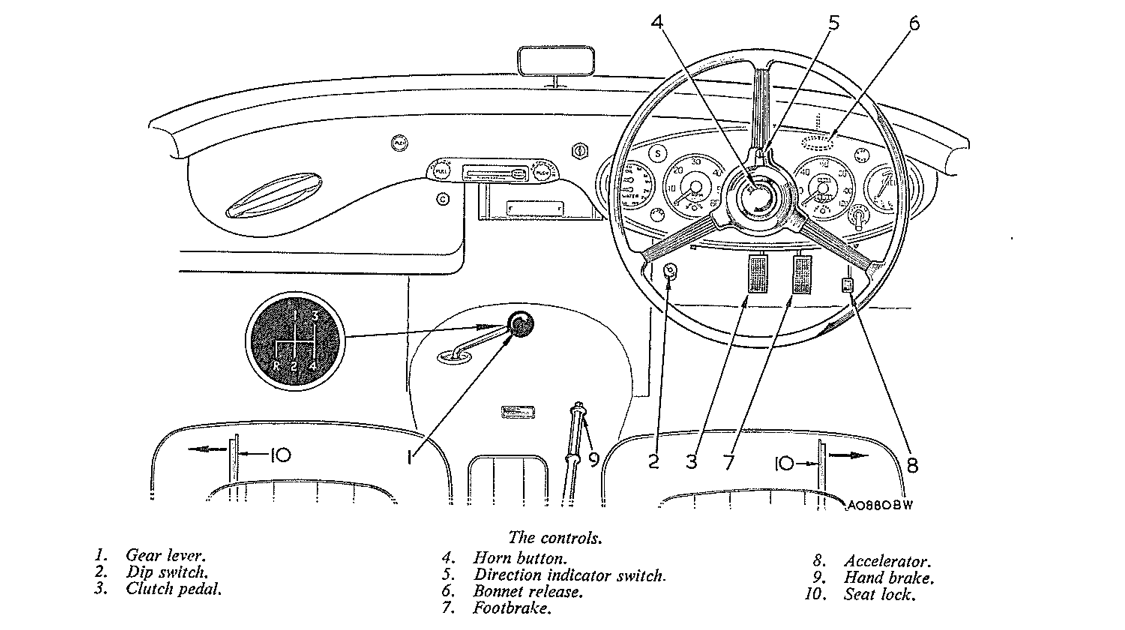
This is situated on the right-hand side of the propeller shaft tunnel, between the seats. To release, pull rearwards slightly and depress the knob in the end of the lever then push fully forward.
Choke or mixture control
To enrich the mixture and assist starting when the engine is cold, pull out the knob marked C. Push it inwards to the normal running position as soon as the engine is warm enough to run without the rich mixture.
Never allow the engine to run for any length of time with the mixture control pulled out.
Some BN7 and BT7 cars have carburetters fitted with a thermostatically operated rich mixture device. This dispenses with the driver-operated mixture control. (See Section DDD1.)
Overdrive switch
The switch is mounted on the fascia panel with the two positions clearly marked.
Ignition switch
Turn the key clockwise to switch on the ignition. Do not leave the switch on when the engine is not running the warning light is a reminder.
The fuel pump and gauge are brought into action by this switch, which is also the master switch for the windscreen wipers and direction indicators. The ignition key also locks the luggage compartment.
Starter switch
Press the button marked S to start the engine, and release it as soon as the engine fires. If the engine fails to start after a few revolutions, do not operate the starter again until the engine is stationary.
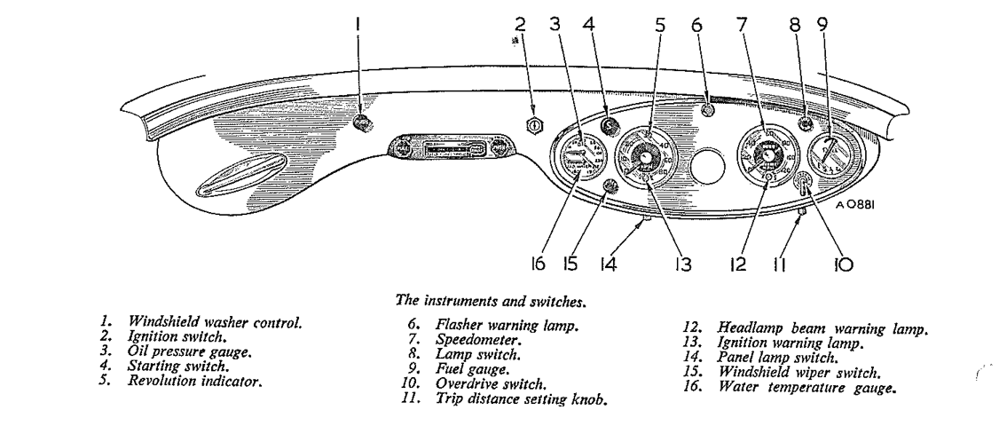
The controls.The instruments and switches.
Lamp switch
Pull out knob marked side-head to switch on the side-lamps and number-plate illuminator. Turn the knob clockwise and pull out again to switch on the headlamps. The headlamps are dipped by foot operation.
Dip switch
This is situated to the left of the clutch pedal. To dip the headlamp beams depress the switch. Depress again to return them to the straight ahead position.
Panel light switch
Slide the switch to the left to illuminate the instruments. This switch operates only when the side-lamps are switched on.
Direction indicator switch
The direction indicators are controlled from the centre of the steering wheel. Normally, after the car has turned a corner, the control is automatically returned to the vertical position and the indicators switched off, but when only a slight turn has been made it may be necessary to return the switch manually.
Horn button
This is mounted at the centre of the steering wheel; it car. be operated independently of the ignition switch.
Windshield wiper switch
Pull out the control marked W to set the wipers in motion. Push in the knob to switch off the motor and park the blades.
The windshield wipers are self-parking and operate only when the ignition is switched on.
Windshield washer control
Push in the knob on the fascia to operate the windshield washer. Set the wipers in motion before operating the cleaning jets.
Battery master switch
This switch, situated in the luggage compartment, is fitted as an anti-theft device. The luggage compartment must of course be locked after the switch bas been turned to the off position,
INSTRUMENTS
Speedometer
Indicates the vehicle speed and total distance. The trip figures at the top of the speedometer face can he reset to zero by pushing up the knob at the bottom of the speedometer and turning it clockwise.
Tachometer
This instrument indicates the revolutions of the engine per minute and thus assists the driver in determining the most effective engine speed range for maximum performance in any gear.
Water temperature gauge
The temperature of the cooling water leaving the cylinder head is indicated by this gauge and should be 185to 194°F. (85 to 90°C.) when the engine is running normally. If the normal running temperature is greatly exceeded the cause must be traced and rectified immediately.
Oil pressure gauge
The pressure of the oil in the lubricating system should be 55 to 60 lb./sq. in. (3.87 to 4.22 kg./sq. cm.) under normal running conditions. Approximately 20 lb./sq. in. (1.4 kg./sq. cm.) should be shown when the engine is idling. Should the gauge fa11 to register any pressure at all, stop the engine immediately and investigate the cause.
Fuel gauge
When the ignition is switched on the gauge indicates the quantity of fuel in the tank.
GENERAL
Warning lamps
When the ignition is switched on the ignition warning lamp located in the tachometer face will glow red. It will fade out again when the engine is started and the speed increased sufficiently for the dynamo to charge the battery.
Should the lamp still glow with increased engine speed, the cause should be investigated immediately.
The main beam warning lamp located in the speedometer face glows dull red or blue (export) when the headlamps are switched on, with the two beams straight ahead. The lamp goes out when the headlamps are dipped.
The direction indicator warning lamp located in the centre and at the top of the instrument panel, flashes green while the direction indicators are operating.
Steering column adjustment (optional extra)
The steering column can be adjusted to suit the driver’s position. To adjust: grip the locking collar immediately behind the steering wheel hub with the hand, hold the rim of the wheel and turn the locking collar clockwise to release its clamping action.
The steering wheel may then be pushed or pulled to the desired position and locked by firmly turning the locking collar in an anti-clockwise direction.
Bonnet lock control
To open the bonnet pull the control handle located behind the fascia panel on the right-hand side. The bonnet will rise an inch or so and will then be held by two spring-loaded safety catches. Insert the fingers, push back the catches simultaneously and raise the bonnet. The bonnet may he supported in the open position by releasing one end of the rod secured to the underside and engaging it in the slot on the left side of the bonnet surround.
When closing the bonnet stow the rod in the retaining clip and exert a downward pressure on the bonnet top until the locking catch is heard to engage.
It is essential that the bonnet release mechanism and safety catches are adequately lubricated to ensure freedom of operation of these components. Should any stiffness occur, it might result in insecure fastening of the bonnet, with a consequent risk of it flying open when the car is in motion.
Luggage compartment
The luggage compartment is locked by the ignition key. Located within this compartment are the spare-wheel, tool kit, battery master switch, and battery (four-seater models).
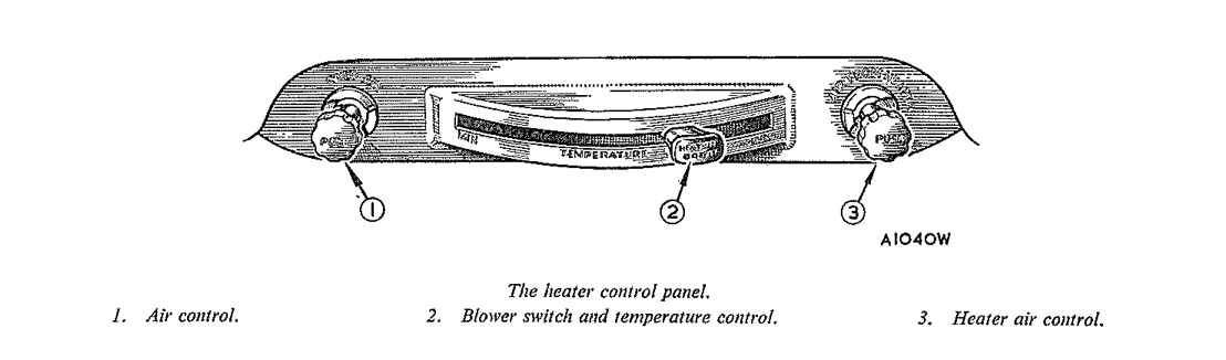
The heater control panel.
Heating and ventilating system
The heating and ventilating system is operated from a control panel situated centrally below the fascia and consisting of two control knobs and a quadrant lever and switch:
(1) The quadrant lever regulates the temperature of the air passing into the car interior. (2) The knob on the end of the quadrant lever, when pulled out, switches on the booster fan. (3) The control knob on the right-hand side of the control panel regulates the supply of air passing through the heater into the car interior. When the knob is pulled right out the supply of air is completely shut off. (4) The control knob on the left-hand side of the control panel regulates the supply of air through the cold air intake duct. This is entirely independent of the heater unit. To admit cold air to the car interior, pull out the knob.
Hinged shutters are provided on the heater air outlet ducts above the driver’s and passenger’s feet. Closing the shutters directs the air flow to the windshield. The air flow to the car interior can also be varied at will.
To remove ice from the windshield close the hinged shutters, move the quadrant lever to the MAX position and switch on the booster fan. All the heated air will now be directed on to the windshield.
Even without the fan switched on air will be forced into the vehicle and on to the windshield by ram effect due to the vehicle’s motion, providing that the controls are set in the appropriate positions. At low speeds or when the vehicle is stationary, particularly if maximum heating or ventilation is required, the booster fan should be switched on.
If necessary the air supply to the vehicle interior can be entirely shut off to prevent the entry of exhaust fumes or dust.
RUNNING-IN SPEEDS
The treatment given to a new car will have an important bearing on its subsequent life, and engine speeds during i this early period must be limited. The following instructions should be strictly adhered to.
During the first 500 miles (800) km.
DO NOT exceed 45 m.p.h. (72 km.p.h.).
DO NOT operate at full throttle in any gear.
DO NOT allow the engine to labour in any gear.
CLAIMS UNDER WARRANTY
Claims for the replacement of material or parts under Warranty must always be submitted to the supplying Distributor or Dealer, or, when this is not possible, to the nearest Distributor or Dealer, informing them of the Vendor’s name and address.
PRESERVATIVE ON EXPORT CARS
To remove the hard film preservative from the external plated parts, a cloth dipped in a solution of equal parts of white spirit and fuel should be used. Take care to keep this solvent from anything other than the plated components.
LOCATION OF MAJOR COMPONENT SERIAL NUMBERS
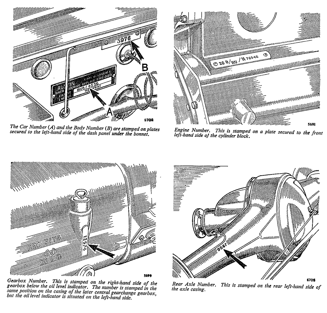
The major components of the vehicle have serial numbers. When in communication with your Distributor or Dealer always quote the car and engine numbers. The registration number is of no assistance and is not required. The engine number is stamped on a plate fixed to the left-hand side of the cylinder block. Other major components have their serial numbers stamped upon them and their locations are illustrated below.
CAR NUMBER IDENTIFICATION CODE (later models)
The car number symbol of Series BN7, BT7 and BJ7 cars consists of three letters and one figure followed by a fifth prefix letter (L) if the vehicle is left-hand drive and then by the serial number of the vehicle.
The first letter when related to the code provides an indication of the make of the vehicle –Healey, etc.
The second letter provides an indication of the model’s cubic capacity.
The third letter indicates the type of body–4-seat touter.
The first figure indicates the series of model, 1, 2, etc. 1st Prefix Letter-Name 2nd Prefix Letter-Model (cubic capacity) A -Anstin M-Morris A -800-999 C.C. G-1000-1399 c c G-M.G. R -Riley B -2000-2999 C.C. H-1400-1999 C.C. H -Healey W-Wolseley D-2000-3999 C.C. L -up to 799 C.C. 3rd Prefix Letter-Body type A -Ambulance J -Convertible 0 -Chassis and Cab U -Pick-up C -Chassis I< -Truck P -Hard top T -4-seat Touret D-Coupe L -Hire-car R-Chassis and Scuttle V -Van E -G.P.O. Engineers M-Limousine S -4-door Saloon W-Dual-purpose G-G.P.O. Mail N-Zseat Tourer 2s-2-door Saloon X -Taxi H -Hearse
4th Prefix-Series of model (1, 2, etc., used to record a major change).
5th Prefix (used when vehicles differ from standard R. H. D.) L-Left-hand drive.
Code Example
H/BN7 1001
POWER UNIT SERIAL NUMBER CODING
The engine number on later models comprises a series of letters and numbers, presenting in code the capacity make and type of unit, ancillaries fitted and the type of compression together with the serial number of the unit
1st Prefix Group – Cubic capacity, make and type
1st Prefix number
1st Prefix letter
2nd Prefix Group – Gearbox and ancillaries
3rd Group – Compression and serial number
IDENTIFICATION OF UNIFIED SCREW THREADS
The general standardization of Unified thread screws makes it necessary to identify all bolts, and set screws with these in order to ensure their being matched with correspondingly threaded components and the fitting of correct replacements.
Identification has been standardized and is effected in the following manner;
Nuts. By a circular groove turned on the end face of the nut or by connected circles stamped on one flat of the hexagon.
Bolts and set screws. By a circular depression turned on the head or by connected circles stamped on one flat of the hexagon.
Wheel stud nuts. By a notch cut in all the corners of the hexagon.
It is of the utmost importance that any nuts, bolts or set screws marked with the above identification are used only in conjunction with associated components having Unified threads and that only replacement parts with Unified threads are used, as these are not interchangeable with Whitworth, BSF, or Metric threads.
Spanners. It is to be noted that all ANF- and Unified-threaded nuts and hexagon-headed bolts are made to the standard American hexagon sizes and that spanners of the appropriate size must be used when tightening or loosening them.
PART NAME ALTERNATIVES
ENGINE
Gudgeon pin
Piston pin. Small-end pin. Wrist pin
Scraper ring
Oil control ring
Core plug
Expansion plug. Welch plug. Sealing disc
Oil sump
Oil pan. Oil reservoir.
CONTROLS
Mixture control
Choke. Strangler.
GEARBOX
Gear lever
Shift lever.
Change speed fork
Shift fork. Selector fork.
First motion shaft
Clutch shaft. First reduction pinion. Main drive pinion. Drive gear.
Layshaft
Countershaft.
AXLE
Crown wheel
Ring gear. Spiral drive gear,
Bevel pinion.
Small pinion. Spiral drive pinion.
U bolts
Spring clips.
Axle shaft
Half-shaft. Hub driving shaft. Jack driving shaft.
Differential gear
Sun wheel
Differential pinion
Planet wheel.
Swivel pin
Pivot pin
Stub axle
Swivel axle
Track-rod
Cross-tube.
Draglink
Side tube. Steering connecting rod.
ELECTRICAL
Dynamo
Generator
Control box
Voltage regulator. Cut-out. Voltage control.
EXHAUST
Silencer
Muffler
BODY
Bonnet
Hood.
Wing
Mudguard. Fender.
FROST PRECAUTIONS
Steps must be taken to prevent the water in the cooling system from freezing during frosty weather. Water, when it freezes, expands, with the result that there is a very considerable risk of bursting either the radiator, heater element, or the cylinder block by the pressure generated. Since no provision is made for draining the heater unit, draining the radiator and cylinder block is not a sufficient safeguard. The cooling system is the of the sealed type and relatively high temperatures are developed inthe radiator upper tank. For this reason anti-freeze solutions having an alcohol base are unsuitable owing to their high evaporation rate producing a rapid loss of coolant and a consequent interruption of circuation.
Only anti-freeze of the ethylene glycol type incorporating the correct type of corrosion inhibitor is suitable and owners are recommended to use Bluecol, Shell, Esso Anti-freeze, or any oher anti-freeze that conforms to specification B.S.3151 or B.S.3152.
The recommended quantities of anti-freeze for different degrees of frost are:
Down to 7º F (=14º C).) 15% solution Quantity 3 pints (1.71 litres)
Down to 0ºF (=18ºC.) 20% solution Quantity 4 pints (2.27 litres)
Where temperatures below 0ºF (-18ºC) are liekly to be encountered, a solution of at least 25 per cent of anti-freeze must be used to ensure immunity from trouble. Consult your local Dealer on this matter.
First decide what degree of frost protection is required before adding the anti-freeze.
Make sure that the cooling system is watertight and examine all joints, renewing any defective rubber hose.
Before adding anti-freeze to the cooling system it is advisable to clean the cooling system thoroughly by swilling out the water passages with a hose inserted in the filler, and with the drain taps open.
Avoid excessive topping up, otherwise there is a risk of losing valuable anti-freeze due to expansion of the solution. Top up only when the system is at its normal running temperature.
Generally speaking, anti-freeze is not injurious to cellulose paint provided it is wiped off in a reasonable time.
Radiator anti-freeze must not be used in the windshield washing equipment.
The seat belt in use showing the correct position for the buckle
B.M.C. SEAT BELTS
Use of belts
The fitting of the seat belts to the car must only be carried out by an authorized Austin Dealer or Distributor.
Adjust the short belt until the attached buckle is located just in front of the hip (see illustration above). The upper part of the long belt passes diagonaally across the chest; the lower part returns around the waist to the floor attachment point. The buckle tongue attached to the long belt should be approximately at the belt centre.
The buckle is fastened by pushing the buckle tongue into the buckle until a positive click is heard. Adjust the long belt until the waist portion is comfortably tight and it is just possible to slide a hand between the uppoer part of the belt and the chest. To release the buckle lift the buckle flap to approximately 90º and exert gentle forward pressure on the belt at the same time.
Fold and stow the long belt clear of the floor area immediately after use to ensure safe exit and entry for the occupants of the car.